Nissan Almera Tino V10. Manual - part 330
EC-146
[QG (WITH EURO-OBD)]
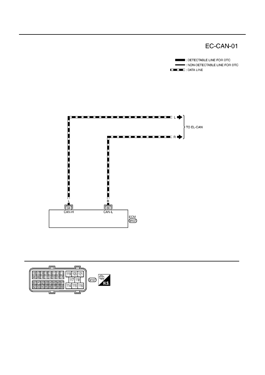
DTC U1000, U1001 CAN COMMUNICATION LINE
Wiring Diagram
EBS00QHK
YEC433A
|
|
|
EC-146 [QG (WITH EURO-OBD)] DTC U1000, U1001 CAN COMMUNICATION LINE Wiring Diagram EBS00QHK YEC433A |