Nissan Almera Tino V10. Manual - part 329
EC-142
[QG (WITH EURO-OBD)]
POWER SUPPLY CIRCUIT FOR ECM
7.
DETECT MALFUNCTIONING PART
Check the following.
●
Harness connectors E105, M10
●
Harness connectors E106, M11 (LHD models)
●
Harness connectors E145, M80 (RHD models)
●
10A fuse
●
15A fuse
●
Harness for open or short between ECM relay and battery
>> Repair open circuit or short to ground or short to power in harness or connectors.
8.
CHECK OUTPUT SIGNAL CIRCUIT FOR OPEN AND SHORT
1.
Check harness continuity between ECM terminal 111 and ECM relay terminal 2.
Refer to Wiring Diagram.
2.
Also check harness for short to ground and short to power.
OK or NG
OK
>> GO TO 9.
NG
>> Repair open circuit or short to ground or short to power in harness or connectors.
9.
CHECK ECM RELAY
Refer to
EC-144, "Component Inspection"
.
OK or NG
OK
>> GO TO
.
NG
>> Replace ECM relay.
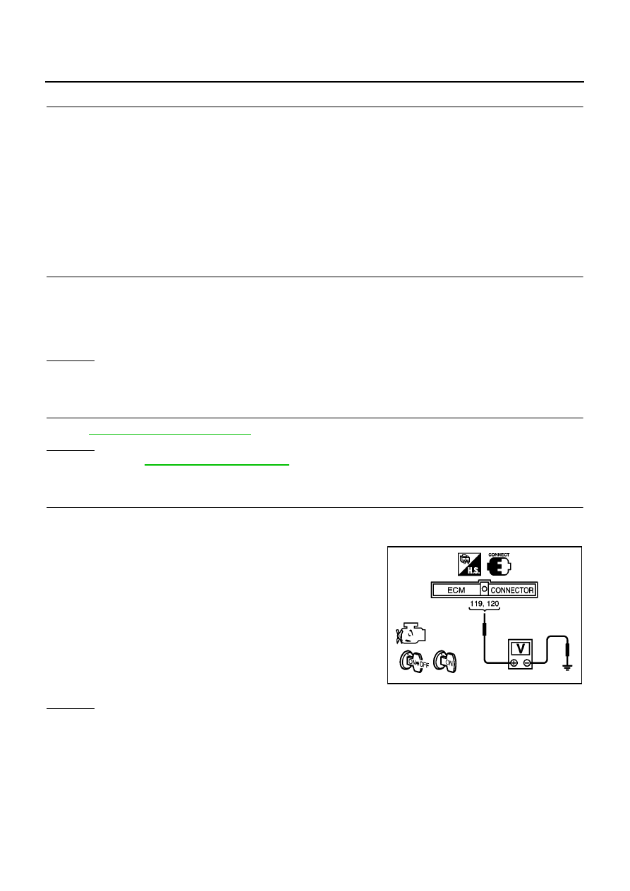
10.
CHECK ECM POWER SUPPLY CIRCUIT-III
1.
Stop engine and wait at least 10 seconds.
2.
Turn ignition switch “ON” and then “OFF”.
3.
Check voltage between ECM terminals 119, 120 and ground
with CONSULT-II or tester.
OK or NG
OK
>> GO TO 15.
NG (Battery voltage does not exist.)>>GO TO 11.
NG (Battery voltage exists for more than a few seconds.)>>GO TO 13.
Continuity should exist.
Voltage:
After turning ignition switch “OFF”, battery
voltage will exist for a few seconds, then
drop approximately 0V.
MBIB0016E