Nissan Almera Tino V10. Manual - part 321
 

  Index      Nissan     Nissan Almera Tino V10 - Service Manual (2003 year)


Search            


Content   ..  319  320  321  322   ..


Nissan Almera Tino V10. Manual - part 321


EC-110

[QG (WITH EURO-OBD)]

TROUBLE DIAGNOSIS

5

B

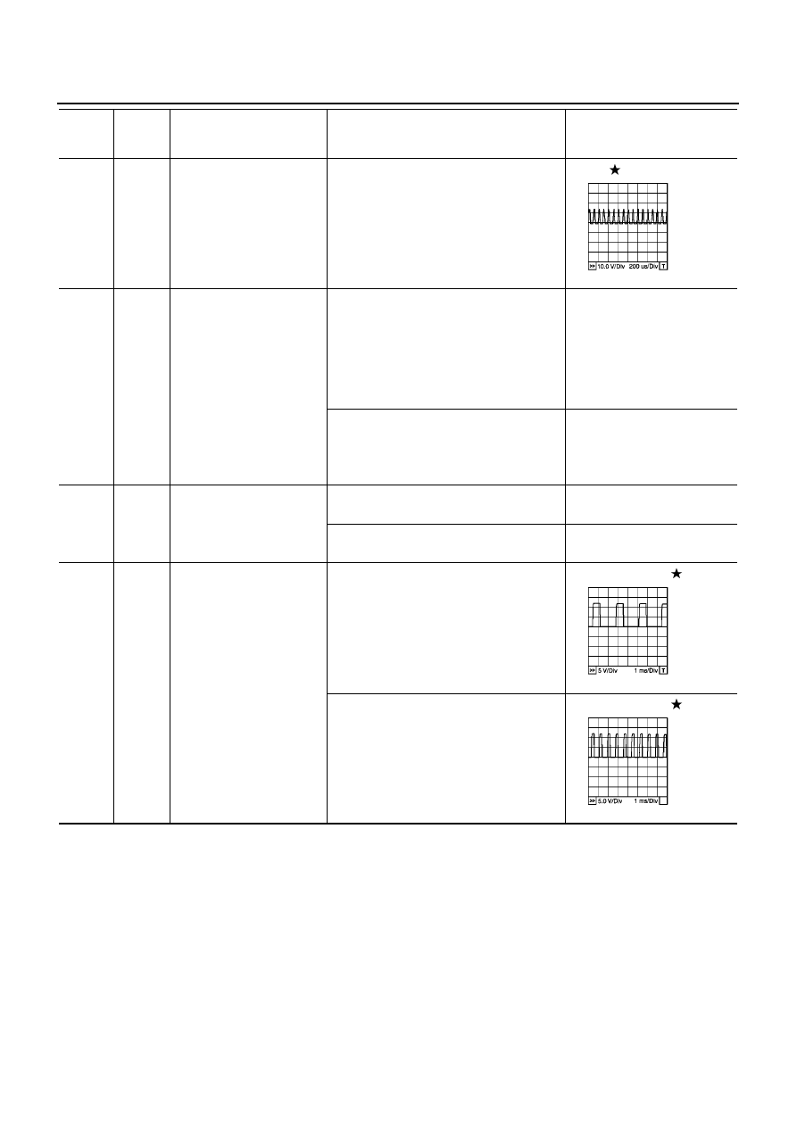
Throttle control motor
(Open)

[Ignition switch “ON”]

●

Engine stopped

●

Shift lever position is “D”

●

Accelerator pedal is depressing

0 - 14V

7

W/R

Heated oxygen sensor 2
heater (bank 2)

[Engine is running]

●

Warm-up condition

●

Engine speed: Below 3,600 rpm after the
following conditions are met.

–

Keeping the engine speed between 3,500
and 4,000 rpm for one minute and at idle
for one minute under no load

0 - 1.0V

[Ignition switch “ON”]

●

Engine stopped

[Engine is running]

●

Engine speed is above 3,600 rpm

BATTERY VOLTAGE
(11 - 14)

12

L

Power steering pressure
sensor

[Engine is running]

●

Steering wheel is being turned

0.5 - 4.0V

[Engine is running]

●

Steering wheel is not being turned

0.4 - 0.8V

13

R

Crankshaft position sensor
(POS)

[Engine is running]

●

Warm-up condition

●

Idle speed

Approximately 3.0V

[Engine is running]

●

Engine speed is 2,000 rpm

Approximately 3.0V

TERMI-

NAL

NO.

WIRE

COLOR

ITEM

CONDITION

DATA (DC Voltage)

PBIB0533E

PBIB0527E

PBIB0528E

TROUBLE DIAGNOSIS

EC-111

[QG (WITH EURO-OBD)]

C

D

E

F

G

H

I

J

K

L

M

A

EC

14

R

Camshaft position sensor
(PHASE)

[Engine is running]

●

Warm-up condition

●

Idle speed

1.0 - 4.0V

[Engine is running]

●

Engine speed is 2,000 rpm.

1.0 - 4.0V

15

W

Knock sensor

[Engine is running]

●

Idle speed

Approximately 2.5V

16

W

Heated oxygen sensor 2
(bank 1)

[Engine is running]

●

Warm-up condition

●

Engine speed is 3,000 rpm quickly after
the following conditions are met.

–

Keeping the engine speed between 3,500
and 4,000 rpm for one minute and at idle
for one minute under no load.

0 - Approximately 1.0V

17

L

Heated oxygen sensor 2
(bank 2)

[Engine is running]

●

Warm-up condition

●

Engine speed is 3,000 rpm quickly after
the following conditions are met.

–

Keeping the engine speed between 3,500
and 4,000 rpm for one minute and at idle
for one minute under no load.

0 - Approximately 1.0V

19

GY/L

EVAP canister purge
volume control solenoid
valve

[Engine is running]

●

Idle speed

BATTERY VOLTAGE

(11 - 14V)

[Engine is running]

●

Engine speed is about 2,000 rpm (More
than 100 seconds after starting engine)

Approximately 10V

TERMI-

NAL

NO.

WIRE

COLOR

ITEM

CONDITION

DATA (DC Voltage)

PBIB0525E

PBIB0526E

PBIB0050E

PBIB0520E

EC-112

[QG (WITH EURO-OBD)]

TROUBLE DIAGNOSIS

22
23
41
42

G/B
R/B
L/B
Y/B

Injector No. 3
Injector No. 1
Injector No. 4
Injector No. 2

[Engine is running]

●

Warm-up condition

●

Idle speed

BATTERY VOLTAGE

(11 - 14V)

[Engine is running]

●

Warm-up condition

●

Engine speed is 2,000 rpm

BATTERY VOLTAGE

(11 - 14V)

24

G

Heated oxygen sensor 1
heater (bank 1)

[Engine is running]

●

Warm-up condition

●

Engine speed is below 3,200 rpm

Approximately 7.0V

[Ignition switch “ON”]

●

Engine stopped

[Engine is running]

●

Engine speed is above 3,200 rpm

BATTERY VOLTAGE
(11 - 14V)

25

R/B

Heated oxygen sensor 1
heater (bank 2)

[Engine is running]

●

Warm-up condition

●

Engine speed is below 3,200 rpm

Approximately 7.0V

[Ignition switch “ON”]

●

Engine stopped

[Engine is running]

●

Engine speed is above 3,200 rpm

BATTERY VOLTAGE
(11 - 14V)

29

B

Camshaft position sensor
(PHASE) ground

[Engine is running]

●

Idle speed

Approximately 0V

30

B

Camshaft position sensor
(POS) ground

[Engine is running]

●

Idle speed

Approximately 0V

34

BR

Intake air temperature
sensor

[Engine is running]

Approximately 0 - 4.8V
Output voltage varies with
intake air temperature.

35

W

Heated oxygen sensor 1
(bank 1)

[Engine is running]

●

Warm-up condition

●

Engine speed is 2,000 rpm.

0 - Approximately 1.0V
(Periodically change)

TERMI-

NAL

NO.

WIRE

COLOR

ITEM

CONDITION

DATA (DC Voltage)

PBIB0529E

PBIB0530E

PBIB0519E

PBIB0519E

TROUBLE DIAGNOSIS

EC-113

[QG (WITH EURO-OBD)]

C

D

E

F

G

H

I

J

K

L

M

A

EC

36

W

Heated oxygen sensor 1
(bank 2)

[Engine is running]

●

Warm-up condition

●

Engine speed is 2,000 rpm.

0 - Approximately 1.0V
(Periodically change)

45

R

Sensor power supply
(Mass air flow sensor)

[Ignition switch “ON”]

Approximately 5V

46

R

Sensor power supply
(Refrigerant pressure
sensor)

[Ignition switch “ON”]

Approximately 5V

47

G

Sensor power supply
(Throttle position sensor)

[Ignition switch “ON”]

Approximately 5V

49

W

Throttle position sensor 1

[Ignition switch “ON”]

●

Engine stopped

●

Shift lever position is “D”

●

Accelerator pedal fully released

More than 0.36V

[Ignition switch “ON”]

●

Engine stopped

●

Shift lever position is “D”

●

Accelerator pedal fully depressed

Less than 4.75V

50

Y

Mass air flow sensor

[Engine is running]

●

Warm-up condition

●

Idle speed

1.0 - 1.7V

[Engine is running]

●

Warm-up condition

●

Engine speed is 2,500 rpm

1.5 - 2.1V

54

B

Sensor ground
(Knock sensor shield circuit)

[Engine is running]

●

Warm-up condition

●

Idle speed

Approximately 0V

57

B

Sensors' ground
(Power steering pressure
sensor/Refrigerant pressure
sensor)

[Engine is running]

●

Warm-up condition

●

Idle speed

Approximately 0V

60
61
79
80

L/R
BR
GY/R
PU

Ignition signal No. 3
Ignition signal No. 1
Ignition signal No. 4
Ignition signal No. 2

[Engine is running]

●

Warm-up condition

●

Idle speed

0 - 0.1V

[Engine is running]

●

Warm-up condition

●

Engine speed is 2,000 rpm

0 - 0.2V

TERMI-

NAL

NO.

WIRE

COLOR

ITEM

CONDITION

DATA (DC Voltage)

PBIB0521E

PBIB0522E


Content   ..  319  320  321  322   ..