Nissan Almera Tino V10. Manual - part 303
EC-38
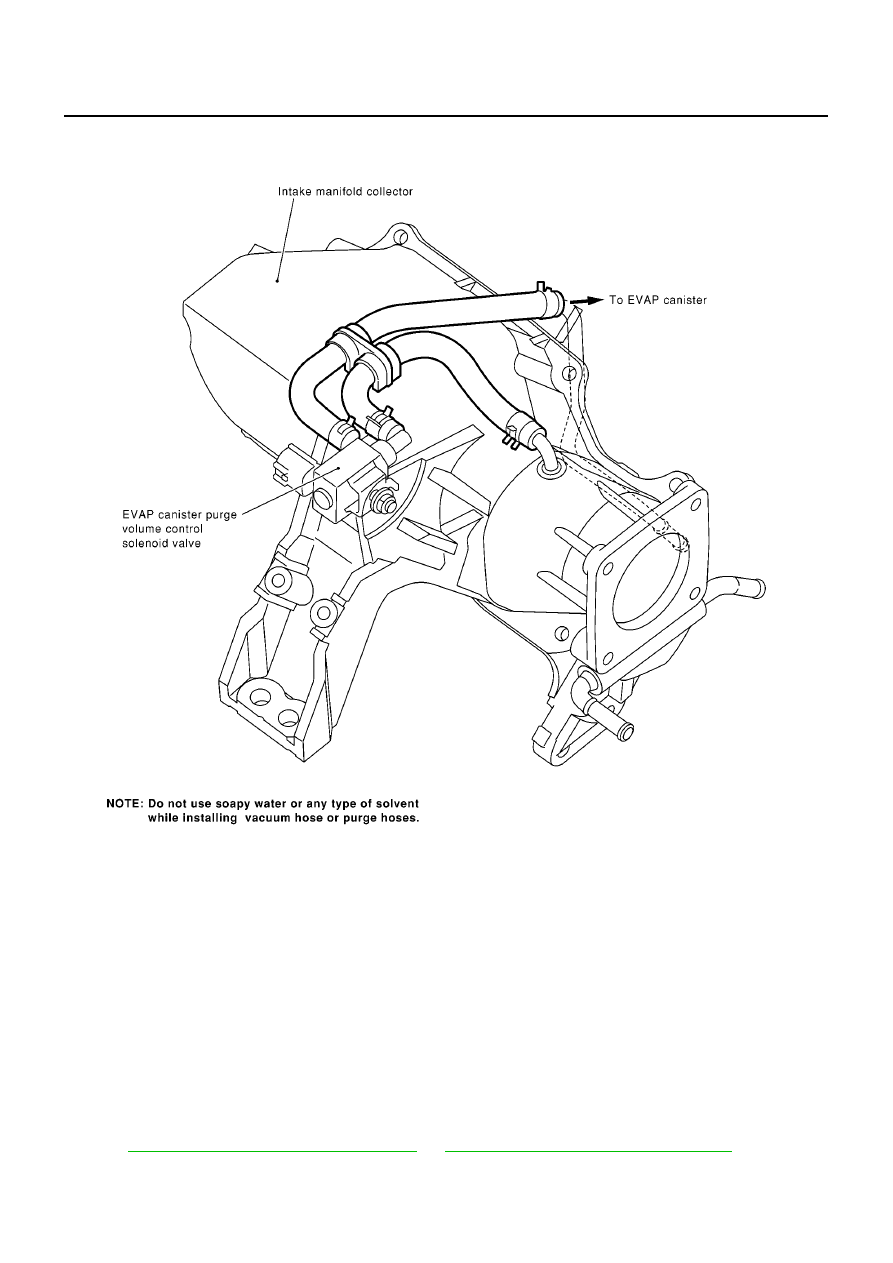
[QG (WITH EURO-OBD)]
ENGINE CONTROL SYSTEM
Vacuum Hose Drawing
EBS00QGD
Refer to
EC-36, "System Diagram - M/T Models"
or
EC-37, "System Diagram - A/T Models"
for Vacuum
Control System.
MBIB0013E
|
|
|
EC-38 [QG (WITH EURO-OBD)] ENGINE CONTROL SYSTEM Vacuum Hose Drawing EBS00QGD Refer to EC-36, "System Diagram - M/T Models" or EC-37, "System Diagram - A/T Models" for Vacuum Control System. MBIB0013E |