Nissan Almera Tino V10. Manual - part 273
Inspection 12 When “ST ANG SEN SIGNAL”
Appears on Self-diagnostic Results Display
=NLBR0191
INSPECTION PROCEDURE
1
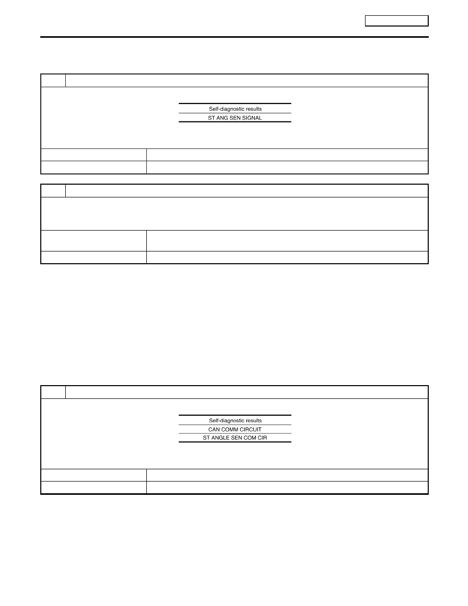
CHECK SELF-DIAGNOSTIC RESULTS (1)
Check self-diagnostic results.
MTBL1630
Does anything besides “ST ANG SEN SIGNAL” appear on self-diagnostic results display?
Yes
©
Inspect and repair the indicated items. Then perform self-diagnosis again.
No
©
Adjust steering angle sensor neutral position. Then GO TO 2.
2
CHECK SELF-DIAGNOSTIC RESULTS (2)
Turin ignition switch OFF, and ON to erase self-diagnostic results, and perform ABS actuator and electric unit (control unit)
self-diagnosis again.
Does anything appear on self-diagnostic results display?
Yes
©
Replace steering angle sensor. Then adjust neutral position and perform self-diagnosis
again.
No
©
INSPECTION END
Inspection 13 CAN Communication System
NLBR0192
INSPECTION PROCEDURE
1
CHECK SELF-DIAGNOSTIC RESULTS (1)
Check self-diagnostic results.
MTBL1631
Do self-diagnostic results indicate anything other than above?
Yes
©
Repair or replace the item indicated.
No
©
GO TO 2.
TROUBLE DIAGNOSIS
ESP/TCS/ABS
Inspection 12 When “ST ANG SEN SIGNAL” Appears on Self-diagnostic Results Display
BR-140