Nissan Almera Tino V10. Manual - part 271


  Index      Nissan     Nissan Almera Tino V10 - Service Manual (2003 year)


Search            


Content   ..  269  270  271  272   ..


Nissan Almera Tino V10. Manual - part 271


4

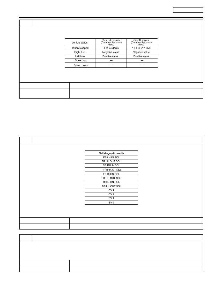
CHECK YAW RATE SENSOR/SIDE G SENSOR

1. Connect yaw rate/side G sensor B66 and ABS actuator and electric unit (control unit) connector E143.
2. Use “Data Monitor” to check if yaw rate sensor/side/decel G sensor are normal.

MTBL1615

OK or NG

OK

©

Perform ABS actuator and electric unit (control unit) self-diagnosis again.

NG

©

Replace the malfunctioning yaw rate sensor/side G sensor, and then perform ABS actua-
tor and electric unit (control unit) self-diagnosis again.

Inspection 7 Solenoid and ESP Change-over
Valve System

NLBR0186

INSPECTION PROCEDURE

1

CHECK SELF-DIAGNOSTIC RESULTS

Check self-diagnostic results.

MTBL1616

Is above displayed in self-diagnosis display items?

Yes

©

GO TO 2.

No

©

INSPECTION END

2

CHECK CONNECTOR

1. Disconnect ABS actuator and electric unit (control unit) connector E143 check terminals for deformation, disconnection,

looseness, and so on. If there is an error, repair or replace terminal.

2. Securely reconnect connectors and perform self-diagnosis.

OK or NG

OK

©

Connector terminal contact is loose, damaged, open or shorted.

NG

©

GO TO 3.

TROUBLE DIAGNOSIS

ESP/TCS/ABS

Inspection 6 Yaw Rate/Side G sensor System (Cont’d)

BR-132

3

CHECK SOLENOID POWER AND GROUND CIRCUIT

1. Disconnect ABS actuator and electric unit (control unit) connector E143.
2. Check voltage between ABS actuator and electric unit (control unit) harness connector E143 and ground.

LFIA0148E

MTBL1617

3. Check resistance between ABS actuator and electric unit (control unit) harness connector E143 and ground.

LFIA0152E

MTBL1618

OK or NG

OK

©

Perform self-diagnosis again. If the same results appear, replace ABS actuator and elec-
tric unit (control unit). Refer to BR-151.

NG

©

Repair harness or connectors.

GI

MA

EM

LC

EC

FE

CL

MT

AT

AX

SU

ST

RS

BT

HA

SC

EL

IDX

TROUBLE DIAGNOSIS

ESP/TCS/ABS

Inspection 7 Solenoid and ESP Change-over Valve System (Cont’d)

BR-133

Inspection 8 Actuator Motor, Motor Relay, and
Circuit

=NLBR0187

INSPECTION PROCEDURE

1

CHECK SELF-DIAGNOSTIC RESULTS (1)

Check self-diagnostic results.

MTBL1619

Is above displayed in self-diagnosis display items?

Yes

©

GO TO 2.

No

©

INSPECTION END

2

CHECK SELF-DIAGNOSTIC RESULTS (2)

1. Disconnect ABS actuator and electric unit (control unit) connector E143. Then reconnect it securely.
2. Perform self-diagnosis again.

Do any self-diagnosis items appear?

Yes

©

GO TO 3.

No

©

Repair or replace the applicable connector.

TROUBLE DIAGNOSIS

ESP/TCS/ABS

Inspection 8 Actuator Motor, Motor Relay, and Circuit

BR-134

3

CHECK ABS MOTOR AND MOTOR RELAY POWER SYSTEM

1. Disconnect ABS actuator and electric unit (control unit) connector E143.
2. Check voltage between ABS actuator and electric unit (control unit) connector E143 and ground.

LFIA0149E

MTBL1620

3. Check resistance between ABS actuator and electric unit (control unit) connector E143 and ground.

LFIA0147E

MTBL1621

OK or NG

OK

©

Perform self-diagnosis again. If the same result appears, replace ABS actuator and elec-
tric unit (control unit). Refer to BR-151.

NG

©

Repair harness or connectors.

GI

MA

EM

LC

EC

FE

CL

MT

AT

AX

SU

ST

RS

BT

HA

SC

EL

IDX

TROUBLE DIAGNOSIS

ESP/TCS/ABS

Inspection 8 Actuator Motor, Motor Relay, and Circuit (Cont’d)

BR-135


Content   ..  269  270  271  272   ..