Nissan Almera Tino V10. Manual - part 272


  Index      Nissan     Nissan Almera Tino V10 - Service Manual (2003 year)


Search            


Content   ..  270  271  272  273   ..


Nissan Almera Tino V10. Manual - part 272


Inspection 9 ABS Actuator and Electric Unit
(Control Unit) Power Supply and Ground
Circuit

=NLBR0188

INSPECTION PROCEDURE

1

CHECK SELF-DIAGNOSTIC RESULTS

Check self-diagnostic results.

MTBL1622

Does “BATTERY VOLTAGE” appear in self-diagnostic results display?

Yes

©

GO TO 2.

No

©

INSPECTION END

2

CHECK STARTING

1. Disconnect ABS actuator and electric unit (control unit) connector E143. Then reconnect it securely.
2. Perform self-diagnosis.

Do any self-diagnosis items appear?

Yes

©

GO TO 3.

No

©

Repair or replace connector.

3

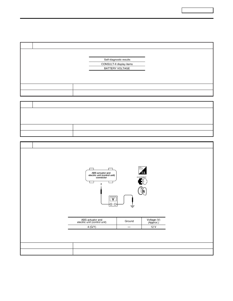
CHECK ABS ACTUATOR AND ELECTRIC UNIT (CONTROL UNIT) POWER SUPPLY

1. Disconnect ABS actuator and electric unit (control unit) connector E143.
2. Turn ignition switch ON (but do not start engine). Check voltage between ABS actuator and electric unit (control unit)

harness connector E143 and ground.

LFIA0151E

MTBL1623

OK or NG

OK

©

GO TO 4.

NG

©

GO TO 5.

TROUBLE DIAGNOSIS

ESP/TCS/ABS

Inspection 9 ABS Actuator and Electric Unit (Control Unit) Power Supply and Ground Circuit

BR-136

4

CHECK ABS ACTUATOR AND ELECTRIC UNIT (CONTROL UNIT) GROUND CIRCUITS

Check ABS actuator and electric unit (control unit) ground circuits.

LFIA0152E

MTBL1624

OK or NG

OK

©

Perform ABS actuator and electric unit (control unit) self-diagnosis again.

NG

©

Repair harness or connectors.

5

CHECK ABS ACTUATOR AND ELECTRIC UNIT (CONTROL UNIT) POWER SYSTEM

1. Disconnect ABS actuator and electric unit (control unit) connector E143.
2. Check continuity between battery positive terminal and ABS actuator and electric unit (control unit) connector E143.

PFIA0461E

MTBL1625

OK or NG

Yes

©

Check for malfunction conditions in battery (terminal looseness, low voltage, etc.) and
alternator.

No

©

Repair harness or connectors.

GI

MA

EM

LC

EC

FE

CL

MT

AT

AX

SU

ST

RS

BT

HA

SC

EL

IDX

TROUBLE DIAGNOSIS

ESP/TCS/ABS

Inspection 9 ABS Actuator and Electric Unit (Control Unit) Power Supply and Ground Circuit (Cont’d)

BR-137

Inspection 10 Stop Lamp Switch System

NLBR0189

INSPECTION PROCEDURE

1

CHECK SELF-DIAGNOSTIC RESULTS

Check self-diagnostic results.

MTBL1626

Is above displayed in self-diagnosis display items?

Yes

©

GO TO 2.

No

©

INSPECTION END

2

CHECK CONNECTOR

1. Disconnect the stop lamp switch connector F30 (QG engine), F12 (YD22DDT engine), F66 (YD22DDTi engine) and

ABS actuator and electric unit (control unit) connector E143 and check terminals for deformation, disconnection,
looseness, and so on. If any malfunction is found, repair or replace terminal.

2. Securely reconnect connectors.
3. Start engine.
4. Repeat pumping brake pedal carefully several times, then perform self-diagnosis again.

OK or NG

OK

©

Connector terminal contact is loose, damaged, open or shorted.

NG

©

GO TO 3.

3

CHECK STOP LAMP SWITCH CIRCUIT

1. Turn ignition switch OFF and disconnect stop lamp switch connector F30 (QG engine), F12 (model with YD22DDT

engine), F66 (YD22DDTi engine) and ABS actuator and electric unit (control unit) connector E143.

YBR374

2. Check continuity between stop lamp switch harness connector F30 (QG engine), F12 (model with YD22DDT engine),

F66 (YD22DDTi engine) and ABS actuator and electric unit (control unit) harness connector E143.

MTBL1627

OK or NG

OK

©

Connect connectors and perform an ABS actuator and electric unit (control unit) self-di-
agnosis.

NG

©

Open or short in harness. Repair or replace harness.

TROUBLE DIAGNOSIS

ESP/TCS/ABS

Inspection 10 Stop Lamp Switch System

BR-138

Inspection 11 Brake Fluid Level Sensor System

=NLBR0190

INSPECTION PROCEDURE

1

CHECK SELF-DIAGNOSTIC RESULTS

1. Check the brake reservoir tank fluid level. If the level is low, add brake fluid.
2. Erase self-diagnostic results and check self-diagnostic results.

MTBL1628

Is above displayed in self-diagnosis display items?

Yes

©

GO TO 2.

No

©

INSPECTION END

2

CHECK CONNECTOR

1. Disconnect the brake fluid level sensor connector E86 and ABS actuator and electric unit (control unit) connector E143

and check terminal for deformation, disconnection, looseness, and so on. If there is any malfunction condition, repair or
replace terminal.

2. Securely reconnect connectors and perform self-diagnosis again.

OK or NG

OK

©

Connector terminal contact is loose, damaged, open or shorted.

NG

©

GO TO 3.

3

CHECK HARNESS BETWEEN THE BRAKE FLUID LEVEL SENSOR AND ABS ACTUATOR AND ELEC-
TRIC UNIT (CONTROL UNIT)

1. Turn ignition switch OFF and disconnect the brake fluid level sensor connector E86, ABS actuator and electric unit

(control unit) connectors E143.

YBR375

2. Check continuity between the brake fluid level sensor connector E86 and ABS actuator and electric unit (control unit)

connector E143 and ground.

MTBL1629

OK or NG

OK

©

Connect connectors and perform an ABS actuator and electric unit (control unit) self-di-
agnosis.

NG

©

If there is an open or short in harness, repair or replace harness.

GI

MA

EM

LC

EC

FE

CL

MT

AT

AX

SU

ST

RS

BT

HA

SC

EL

IDX

TROUBLE DIAGNOSIS

ESP/TCS/ABS

Inspection 11 Brake Fluid Level Sensor System

BR-139


Content   ..  270  271  272  273   ..