Nissan Almera Tino V10. Manual - part 265
 

  Index      Nissan     Nissan Almera Tino V10 - Service Manual (2003 year)


Search            


Content   ..  263  264  265  266   ..


Nissan Almera Tino V10. Manual - part 265


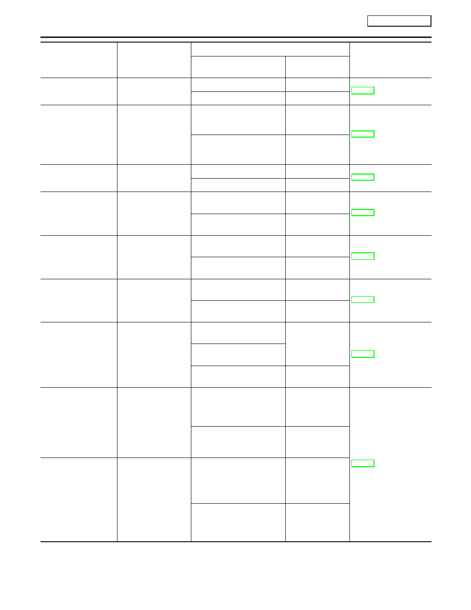
Monitor item

Display content

Data monitor

Error inspection checklist

Condition

Reference value in

normal operation

STOP LAMP SW

Brake pedal operation

Brake pedal depressed

ON

BR-138

Brake pedal not depressed

OFF

OFF SW

ESP OFF switch
ON/OFF status

ESP OFF switch ON
(When ESP OFF indicator
lamp is ON)

ON

BR-142

ESP OFF switch OFF
(When ESP OFF indicator
lamp is OFF)

OFF

ABS WARN LAMP

ABS warning lamp ON
condition (Note 2)

ABS warning lamp ON

ON

BR-122

ABS warning lamp OFF

OFF

MOTOR RELAY

Operation status of
motor and motor relay

Ignition switch ON or engine
running (ABS not operated)

OFF

BR-134

Ignition switch ON or engine
running (ABS operated)

ON

ACTUATOR RLY

Actuator relay opera-
tion status

Vehicle stopped (Ignition
switch ON)

OFF

BR-134

Vehicle stopped (Engine run-
ning)

ON

OFF LAMP

ESP OFF indicator
lamp status (Note 3)

When ESP OFF indicator
lamp is ON

ON

BR-142

When ESP OFF indicator
lamp is OFF

OFF

SLIP LAMP

SLIP indicator lamp
status (Note 4)

When SLIP indicator lamp is
ON

ON

BR-122

When SLIP indicator lamp is
blinking

When SLIP indicator lamp is
OFF

OFF

FR LH IN SOL
FR LH OUT SOL
FR RH IN SOL
FR RH OUT SOL
RR RH IN SOL
RR RH OUT SOL
RR LH IN SOL
RR LH OUT SOL

Solenoid valve opera-
tion

Actuator (solenoid) is active
(“ACTIVE TEST” with CON-
SULT-II) or actuator relay is
inactive (in fail-safe mode).

ON

BR-132

When actuator (solenoid) is
not active and actuator relay
is active (ignition switch ON).

OFF

CV1
CV2
SV1
SV2

ESP/TCS switch-over
valve status

When actuator (switch-over
valve) is active (“ACTIVE
TEST” with CONSULT-II) or
actuator relay is inactive
(when in fail-safe mode).

ON

When actuator (switch-over
valve) is not active and actua-
tor relay is active (ignition
switch ON).

OFF

TROUBLE DIAGNOSIS

ESP/TCS/ABS

Control Unit Input/Output Signal Standard (Cont’d)

BR-108

Monitor item

Display content

Data monitor

Error inspection checklist

Condition

Reference value in

normal operation

FLUID LEV SW

ON/OFF status of
brake fluid level switch

When brake fluid level switch
ON

ON

BR-139

When brake fluid level switch
OFF

OFF

ESP FAIL SIG
TCS FAIL SIG
ABS FAIL SIG
EBD FAIL SIG

Fail signal status

ESP fail
TCS fail
ABS fail
EBD fail

ON

ESP system
TCS system
ABS system
EBD system

ESP normal
TCS normal
ABS normal
EBD normal

OFF

EBD WARN LAMP

Brake warning lamp on
condition (Note 5)

Brake warning lamp ON

ON

BR-122

Brake warning lamp OFF

OFF

EBD SIGNAL

EBD operation

EBD active

ON

EBD not active

OFF

ABS SIGNAL

ABS operation

ABS active

ON

ABS not active

OFF

TCS SIGNAL

TCS operation

TCS active

ON

TCS not active

OFF

ESP SIGNAL

ESP operation

ESP active

ON

ESP not active

OFF

CRANKING SIG

CRANKING status

Cranking

ON

Not cranking

OFF

CAN COMM

CAN communications
condition

CAN communication normal

OK

BR-140

CAN communication error

NG

CAN CIRC 1

CAN communications
condition

CAN communication normal

OK

CAN communication error

UNKWN

CAN CIRC 2

CAN communications
condition

CAN communication normal

OK

CAN communication error

UNKWN

CAN CIRC 3

CAN communications
condition

CAN communication normal

UNKWN

CAN communication error

CAN CIRC 4

CAN communications
condition

CAN communication normal

UNKWN

CAN communication error

CAN CIRC 5

CAN communications
condition

CAN communication normal

OK

CAN communication error

UNKWN

CAN CIRC 6

CAN communications
condition

CAN communication normal

UNKWN

CAN communication error

CAN CIRC 7

CAN communications
condition

CAN communication normal

UNKWN

CAN communication error

GI

MA

EM

LC

EC

FE

CL

MT

AT

AX

SU

ST

RS

BT

HA

SC

EL

IDX

TROUBLE DIAGNOSIS

ESP/TCS/ABS

Control Unit Input/Output Signal Standard (Cont’d)

BR-109

Note 1: Confirm tire pressure is normal.
Note 2: ON/OFF timing of ABS warning lamp
ON: For approximately 2 seconds after ignition switch is turned ON, or when a malfunction is detected.
OFF: Approximately 2 seconds after ignition switch is turned ON (when system is in normal operation) condition by ESP.
Note 3: ON/OFF timing of ESP OFF indicator lamp
ON: For approximately 2 seconds after ignition switch is turned ON, or when a malfunction is detected and ESP OFF switch is ON.
OFF: Approximately 2 seconds after ignition switch is turned ON (when system is in normal operation.) And when ESP OFF switch is
OFF.
Note 4: SLIP indicator lamp ON/OFF timing
ON: For approximately 2 seconds after ignition switch is turned ON, or when a malfunction is detected.
OFF: Approximately 2 seconds after ignition switch is turned ON (when system is in normal operation) and ESP/TCS function is not
activated.
Blinking: ESP/TCS function is active during driving
Note 5: Serves as EBD warning lamp.

CONSULT-II Functions

NLBR0177

CAUTION:

I

Do not use the “function test” for diagnosis. For more
information, refer to the separate volume “CONSULT-II
OPERATION MANUAL (Function Test)”.

I

When the CONSULT-II is connected and communicating,
ABS warning lamp, SLIP indicator lamp, and ESP OFF
indicator lamp turn on, and when the communication is
interrupted, the lamps will turn off after approximately 2 to
3 sec.

I

When self-diagnosis, data monitor, or active test functions
are being executed, EBD, ABS, TCS, and ESP control is
not conducted.

I

When using CONSULT-II to conduct ABS actuator and
electric unit (control unit) self-diagnosis, active test, work
support, etc., first stop engine, connect the CONSULT-II,
and select “ABS”.

I

When CONSULT-II is used, ABS warning lamp, ESP OFF
indicator lamp, SLIP indicator lamp may be turned
ON/OFF.

I

When an error is shown by the CONSULT-II SELF-DIAG
RESULTS and CONSULT-II is used to conduct an active
test, an engine system malfunction may be shown, but
restarting engine will return the status to normal.

CONSULT-II FUNCTION APPLICATION TABLE (MAIN
ITEMS)

NLBR0177S01

Item

Self-diagnosis

Data monitor

Active test

Wheel sensors

×

×

Stop lamp switch

×

×

Solenoid valves

×

×

×

Switch-over solenoid valves

×

×

TROUBLE DIAGNOSIS

ESP/TCS/ABS

Control Unit Input/Output Signal Standard (Cont’d)

BR-110

Item

Self-diagnosis

Data monitor

Active test

Yaw rate/side G sensor

×

×

Pressure sensor

×

×

Steering angle sensor

×

×

ABS actuator relay

×

×

ABS motor relay

×

×

ABS warning lamp

×

Battery voltage

×

×

ABS actuator and electric unit (control
unit)

×

ABS actuator motor

×

×

×

CAN communication

×

×

Engine speed signal

×

ESP OFF switch

×

ESP OFF indicator lamp

×

SLIP indicator lamp

×

Accelerator pedal position signal

×

Selector lever position

×

EBD/ABS/TCS/ESP signals

×

×

Brake fluid level switch

×

×

Engine signals

×

Brake warning lamp (Note)

×

×

: Applicable

–: Not applicable
Note: Serves as EBD warning lamp.

CONSULT-II BASIC OPERATION PROCEDURE

NLBR0177S02

1.

Turn ignition switch OFF.

MBIB0906E

2.

Connect CONSULT-II and CONSULT-II CONVERTER to the
data link connector.

CAUTION:

If CONSULT-II is used with no connection of CONSULT-II
CONVERTER, malfunctions might be detected in self-diagno-
sis depending on control unit which carry out CAN communi-
cation.
3.

Turn ignition switch ON.

GI

MA

EM

LC

EC

FE

CL

MT

AT

AX

SU

ST

RS

BT

HA

SC

EL

IDX

TROUBLE DIAGNOSIS

ESP/TCS/ABS

CONSULT-II Functions (Cont’d)

BR-111


Content   ..  263  264  265  266   ..