Nissan Almera Tino V10. Manual - part 244
SBR633E
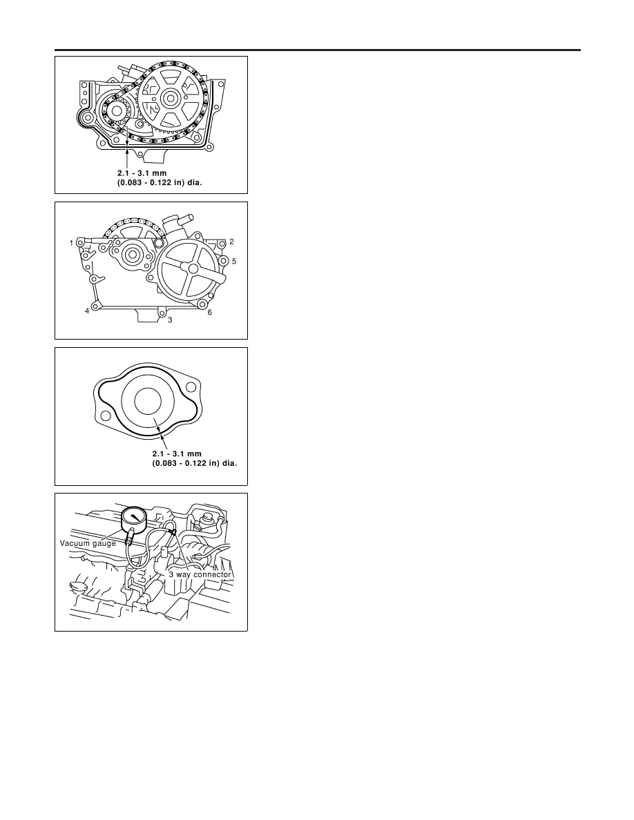
Installation
NLBR0124
1.
Assemble vacuum pump and cylinder head rear cover
assembly, referring to “Component” in the next page.
2.
Install vacuum pump and cylinder head rear cover assembly to
cylinder head.
a.
Apply ThreeBond 1207C (KP510 00150) without breaks to the
location shown in the figure to the left.
SBR632E
b.
Tighten the mounting bolts in the numerical order shown by the
figure to the left.
3.
Install rear cam sprocket installation bolts.
4.
Remove sprocket retaining two M6 bolts.
I
M6 bolts will be used for installation.
5.
Tighten rear cam sprocket installation bolts.
I
Camshaft should not be fixed. Using engine inner resistance,
tighten installation bolts.
SBR634E
6.
Install cylinder head rear cover plate.
I
Apply ThreeBond 1207C (KP510 00150) without breaks to the
location shown by the figure to the left.
7.
Install parts in the reverse order of removal.
CAUTION:
If the engine is started with vacuum pump released (vacuum
hose disconnected), it causes increase of blowby gas amount,
and engine damage may result. When starting the engine, be
sure to close vacuum circuit.
SBR611E
Inspection
NLBR0125
I
Remove vacuum hose. Then, connect vacuum gauge with
three-way connector.
I
Install three-way connector to the area where vacuum pump
negative pressure can be directly measured. (The figure
shown an example.)
I
Start the engine, then measure negative pressure.
Standard: −86.6 to −101.3 kPa (−866 to −1,013 mbar,
−650 to −760 mmHg, −25.59 to −29.92 inHg)
I
If it is not within standard, inspect for suction of air in the middle
of route and measure it again.
I
If it is still not within standard value, replace the vacuum pump.
VACUUM PUMP
Installation
BR-24