Nissan Almera Tino V10. Manual - part 235


  Index      Nissan     Nissan Almera Tino V10 - Service Manual (2003 year)


Search            


Content   ..  233  234  235  236   ..


Nissan Almera Tino V10. Manual - part 235


ATC-136

REFRIGERANT LINES

4.

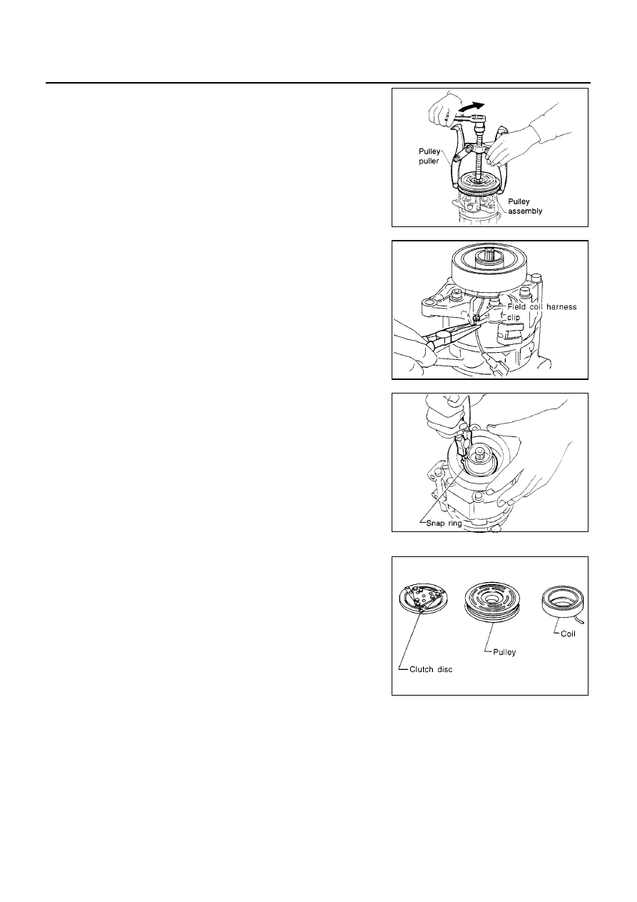
Position the center pulley puller on the end of the drive shaft,
and remove the pulley assembly using any commercially avail-
able pulley puller.
To prevent the pulley groove from being deformed, the puller
claws should be positioned into the edge of the pulley assembly.

5.

Remove the field coil harness clip using a pair of pliers.

6.

Remove the snap ring using external snap ring pliers.

Inspection

Clutch disc
If the contact surface shows signs of damage due to excessive heat,
replace clutch disc and pulley.
Pulley
Check the appearance of the pulley assembly. If the contact surface
of pulley sows signs of excessive grooving, replace clutch disc and
pulley. The contact surfaces of the pulley assembly should be
cleaned with a suitable solvent before reinstallation.

Coil

Check coil for loose connection or cracked insulation.

INSTALLATION

1.

Install the field coil.

RHA139E

RHA125F

RHA145E

RHA126F

REFRIGERANT LINES

ATC-137

C

D

E

F

G

H

I

K

L

M

A

B

ATC

Be sure to align the coil

s pin with the hole in the compressor

s

front head.

2.

Install the field coil harness clip using a screwdriver.

3.

Install the pulley assembly using the installer and a hand press,
and then install the snap ring using snap ring pliers.

4.

Install the clutch disc on the drive shaft, together with the original
shim(s). Press the clutch disc down by hand.

5.

Using the holder to prevent clutch disc rotation.

After tightening the bolt, check that the pulley rotates smoothly.

6.

Check clearance around the entire periphery of clutch disc.

If the specified clearance is not obtained, replace adjusting
spacer and readjust.

RHA142E

RHA143EA

RHA127F

Tightening torque

: 14 N·m (1.4 kg-m, 10 ft-lb)

RHA086E

Disc to pulley clear-
ance

: 0.3 - 0.6 mm (0.012 - 0.024 in)

RHA087E

ATC-138

REFRIGERANT LINES

Break-In Operation

When replacing compressor clutch assembly, always carry out the break-in operation. This is done by engag-
ing and disengaging the clutch about thirty times. Break-in operation raises the level of transmitted torque.

Low-pressure Flexible Hose

EJS0031E

REMOVAL

1.

Use refrigerant collecting equipment (for HFC-134a) to dis-
charge refrigerant.

2.

Remove the clip from the low-pressure flexible hose.

3.

Remove the mounting bolts from the low-pressure flexible hose.

4.

Remove the low-pressure flexible hose.

CAUTION:

Cap or wrap the joint of the pipe with suitable material such
as vinyl tape to avoid the entry of air.

INSTALLATION

CAUTION:

Replace the O-ring of the low-pressure flexible hose with a new one, then apply compressor oil to
it when installing it.

When pouring refrigerant, check for leaks.

High-pressure Flexible Hose

EJS0031F

REMOVAL

1.

Use refrigerant collecting equipment (for HFC-134a) to dis-
charge refrigerant.

2.

Remove the clip from high-pressure flexible hose.

3.

Remove the mounting bolt and nut from the high-pressure flexi-
ble hose, then remove it.

CAUTION:

Cap or wrap the joint of the pipe with suitable material such
as vinyl tape to avoid the entry of air.

RJIA1731E

RJIA0185E

Low-pressure flexible hose and bolts mounting the high-pressure pipe (evapo-
rator side)

Tightening torque

:2.9 - 5.9 N·m (0.29 - 0.6 kg-m, 26 - 52 in-lb)

Nut (Bolt) mounting the low-pressure flexible hose (compressor side)

Tightening torque

:7.8 - 19.6 N·m (0.8 - 2.0 kg-m, 70 - 173 in-lb)

RJIA1735E

REFRIGERANT LINES

ATC-139

C

D

E

F

G

H

I

K

L

M

A

B

ATC

INSTALLATION

CAUTION:

Replace the O-ring of the high-pressure flexible hose with a new one, then apply compressor oil to
it when installing it.

When pouring refrigerant, check for leaks.

High-pressure Pipe

EJS0031G

REMOVAL

1.

Use refrigerant collecting equipment (for HFC-134a) to dis-
charge refrigerant.

2.

Remove the low-pressure flexible hose. Refer to

ATC-138,

"Low-pressure Flexible Hose"

.

3.

Remove the high-pressure pipe from the clip.

4.

Remove the mounting bolt from the high-pressure pipe.

5.

Remove the high-pressure pipe.

CAUTION:

Cap or wrap the joint of the pipe with suitable material such
as vinyl tape to avoid the entry of air.

INSTALLATION

CAUTION:

Replace the O-ring of the high-pressure pipe and low-pressure flexible hose with a new one, then
apply compressor oil to it when installing it.

When pouring refrigerant, check for leaks.

Bolt and nut mounting the high-pressure flexible hose

Tightening torque

:7.8 - 19.6 N·m (0.8 - 2.0 kg-m, 70 - 173 in-lb)

RJIA1720E

RJIA0030E

Bolts mounting the high-pressure pipe (condenser side, evaporator side)

Tightening torque

:2.9 - 5.9 N·m (0.29 - 0.6 kg-m, 26 - 52 in-lb)


Content   ..  233  234  235  236   ..