Nissan Almera Tino V10. Manual - part 229
ATC-112
SUNLOAD SENSOR
SUNLOAD SENSOR
PFP:27721
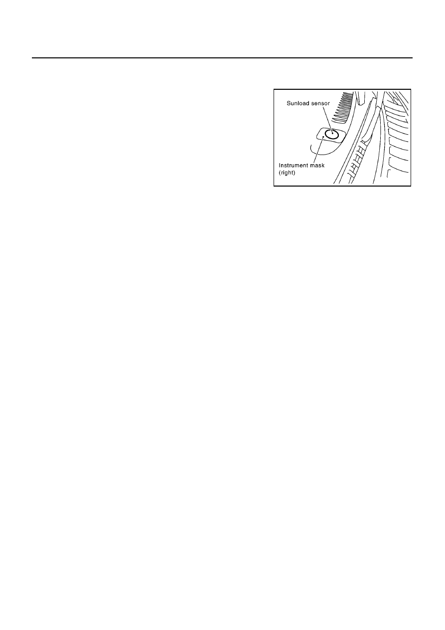
Removal and Installation
EJS0030W
1.
Remove instrument mask (passenger side).
2.
Remove the sunload sensor.
RJIA2330E
|
|
|
ATC-112 SUNLOAD SENSOR SUNLOAD SENSOR PFP:27721 Removal and Installation EJS0030W 1. Remove instrument mask (passenger side). 2. Remove the sunload sensor. RJIA2330E |