Nissan Almera Tino V10. Manual - part 192


  Index      Nissan     Nissan Almera Tino V10 - Service Manual (2003 year)


Search            


Content   ..  190  191  192  193   ..


Nissan Almera Tino V10. Manual - part 192


AT-492

[ALL]

REPAIR FOR COMPONENT PARTS

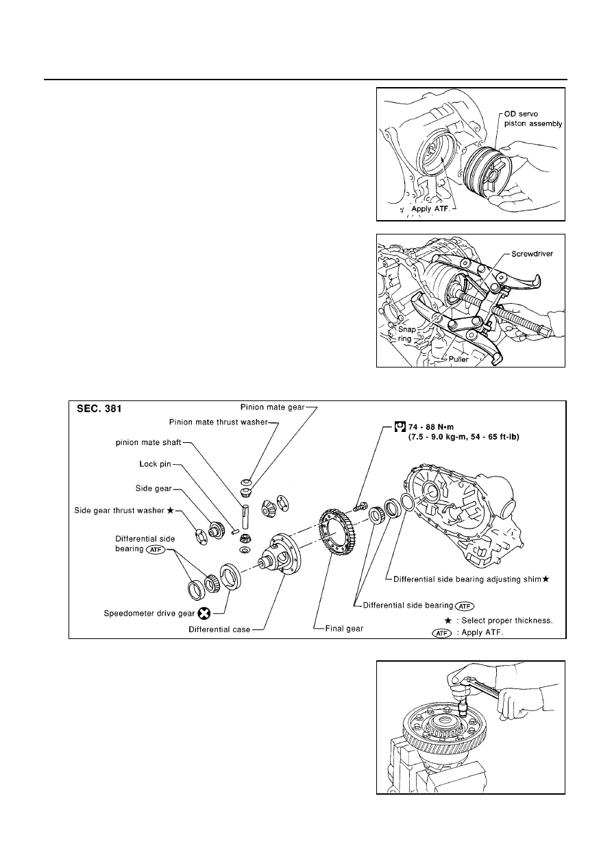
10. Install OD servo piston assembly to transmission case.

Apply ATF to O-ring of band servo piston and transmis-
sion case.

11. Install band servo piston snap ring to transmission case.

Final Drive

ECS009CT

COMPONENTS

DISASSEMBLY

1.

Remove final gear.

AAT692

SAT288D

MCIB9024E

SMT505B

REPAIR FOR COMPONENT PARTS

AT-493

[ALL]

D

E

F

G

H

I

J

K

L

M

A

B

AT

2.

Press out differential side bearings.

Be careful not to mix up the right and left bearings.

3.

Remove speedometer drive gear.

4.

Drive out pinion mate shaft lock pin.

5.

Draw out pinion mate shaft lock pin.

6.

Remove pinion mate gears and from differential case.

SAT312D

SAT313D

SAT904DA

SAT316D

AT-494

[ALL]

REPAIR FOR COMPONENT PARTS

INSPECTION
Gear, Washer, Shaft and Case

Check mating surfaces of differential case, side gears and pin-
ion mate gears.

Check washers for wear.

Bearings

Make sure bearings roll freely and are free from noise, cracks,
pitting or wear.

When replacing taper roller bearing, replace outer and inner
race as a set.

ASSEMBLY

1.

Install side gear and thrust washers in differential case.

2.

Install pinion mate gears and thrust washers in differential case
while rotating them.

When inserting, be careful not to damage pinion mate
gear washers.

Apply ATF to any parts.

3.

Measure clearance between side gear and differential case with
washers using the following procedure:

a.

Set Tool and dial indicator on side gear.

MCIB9022E

SPD715

SAT318D

SAT902D

REPAIR FOR COMPONENT PARTS

AT-495

[ALL]

D

E

F

G

H

I

J

K

L

M

A

B

AT

b.

Move side gear up and down to measure dial indicator deflec-
tion. Always measure indicator deflection on both side gears.

c.

If not within specification, adjust clearance by changing thickness of differential side gear thrust washers.

4.

Install lock pin.

Make sure that lock pin is flush with case.

5.

Install speedometer drive gear on differential case.

Align the projection of speedometer drive gear with the
groove of differential case.

6.

Install final gear and tighten fixing bolts in a numerical order.

Clearance between side gear and differential case
with washer:

0.1 - 0.2 mm (0.004 - 0.008 in)

SMT616

Differential side gear thrust washers:

Refer to

AT-519, "SERVICE DATA AND SPECIFICA-

TIONS (SDS)"

.

SAT904D

SAT313D

SAT326D


Content   ..  190  191  192  193   ..