Nissan Almera Tino V10. Manual - part 183


  Index      Nissan     Nissan Almera Tino V10 - Service Manual (2003 year)


Search            


Content   ..  181  182  183  184   ..


Nissan Almera Tino V10. Manual - part 183


AT-456

[ALL]

REPAIR FOR COMPONENT PARTS

1-2 Accumulator Valve
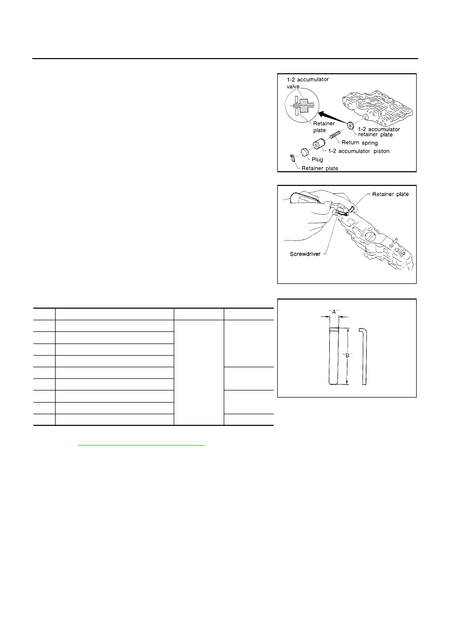
Install 1-2 accumulator valve. Align 1-2 accumulator retainer
plate from opposite side of control valve body.

Install return spring, 1-2 accumulator piston and plug.

1.

Install retainer plates.

Install retainer plate while pushing plug or return spring.

Retainer Plate (Upper Body)

Unit: mm (in)

Install proper retainer plates.
Refer to

AT-453, "Control Valve Upper Body"

.

SAT142D

SAT143D

No.

Name of control valve

Width A

Length B

22

Pilot valve

6.0 (0.236)

21.5 (0.846)

30

1st reducing valve

34

3-2 timing valve

8

Torque converter relief valve

17

1-2 accumulator valve

38.5 (1.516)

25

1-2 accumulator piston

5

Overrun clutch reducing valve

24.0 (0.945)

21

Cooler check valve

13

Torque converter clutch control valve

28.0 (1.102)

SAT086F

REPAIR FOR COMPONENT PARTS

AT-457

[ALL]

D

E

F

G

H

I

J

K

L

M

A

B

AT

Control Valve Lower Body

ECS009CL

COMPONENTS

Numbers preceding valve springs correspond with those shown in

AT-519, "SERVICE DATA AND SPECIFI-

CATIONS (SDS)"

.

1.

Control valve lower body

2.

Return spring

3.

Shift valve B

4.

Plug

5.

Retainer plate

6.

Pressure modifier valve

7.

Return spring

8.

Parallel pin

9.

Sleeve

10. Piston

11.

Return spring

12. Retainer plate

13. Manual valve

14. Retainer plate

15. Sleeve

16. Plug

17. Spring seat

18. Return spring

19. Pressure regulator valve

20. Retainer plate

21. Plug

22. Overrun clutch control valve

23. Return spring

24. Retainer plate

25. Plug

26. Accumulator control valve

27. Return spring

28. Retainer plate

29. Return spring

30. Shift valve A

31. Retainer plate

32. Plug

33. Plug

34. Return spring

35. Shuttle control valve

SAT864J

AT-458

[ALL]

REPAIR FOR COMPONENT PARTS

DISASSEMBLY

Remove valves at retainer plate.
For removal procedures, refer to

AT-454, "DISASSEMBLY"

.

INSPECTION
Valve Springs

Check each valve spring for damage or deformation. Also mea-
sure free length and outer diameter.

Replace valve springs if deformed or fatigued.

Control Valves

Check sliding surfaces of control valves, sleeves and plugs for damage.

ASSEMBLY

Install control valves.
For installation procedures, refer to

AT-455, "ASSEMBLY"

.

Retainer Plate (for control valve lower body)

Unit: mm (in)

Install proper retainer plates.
Refer to

AT-457, "Control Valve Lower Body"

.

SAT872J

Inspection standard

:Refer to

AT-519, "SERVICE DATA

AND SPECIFICATIONS (SDS)"

.

SAT138D

SAT872J

Name of control valve

No.

Length A

Length B

Type

Pressure regulator valve

14

6.0

(0.236)

28.0

(1.102)

I

Accumulator control valve

24

Shift valve A

28

Overrun clutch control valve

20

Pressure modifier valve

12

Shuttle control valve

31

Shift valve B

5

II

SAT089F

REPAIR FOR COMPONENT PARTS

AT-459

[ALL]

D

E

F

G

H

I

J

K

L

M

A

B

AT

Reverse Clutch

ECS009CM

COMPONENTS

DISASSEMBLY

1.

Check operation of reverse clutch

a.

Install seal ring onto drum support of oil pump cover and install
reverse clutch assembly. Apply compressed air to oil hole.

b.

Check to see that retaining plate moves to snap ring.

c.

If retaining plate does not contact snap ring:

D-ring might be damaged.

Oil seal might be damaged.

Fluid might be leaking past piston check ball.

2.

Remove snap ring.

3.

Remove drive plates, driven plates, retaining plate, and dish
plates.

4.

Set Tool on spring retainer and remove snap ring from reverse
clutch drum while compressing return springs.

Set Tool directly over springs.

Do not expand snap ring excessively.

5.

Remove spring retainer and return springs.

SAT485JA

SAT155D

SAT156D

AAT489


Content   ..  181  182  183  184   ..