Nissan Almera Tino V10. Manual - part 180
AT-444
[ALL]
REPAIR FOR COMPONENT PARTS
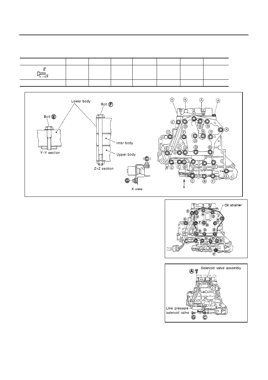
DISASSEMBLY
●
Disassemble upper, inter and lower bodies.
Bolt length, number and location:
F: Reamer bolt and nut
1.
Remove bolts A, D and F, and remove oil strainer from control
valve assembly.
2.
Remove solenoid valve assembly and line pressure solenoid
valve from control valve assembly.
●
Be careful not to lose the line pressure solenoid valve
spring.
Bolt symbol
A
B
C
D
E
F
G
Bolt length “
”
13.5 mm
(0.531 in)
58.0 mm
(2.283 in)
40.0 mm
(1.575 in)
66.0 mm
(2.598 in)
33.0 mm
(1.299 in)
78.0 mm
(3.071 in)
18.0 mm
(0.709 in)
Number of bolts
6
3
6
11
2
2
1
SAT869J
SAT083F
SAT316GA