Nissan Almera Tino V10. Manual - part 98


  Index      Nissan     Nissan Almera Tino V10 - Service Manual (2003 year)


Search            


Content   ..  96  97  98  99   ..


Nissan Almera Tino V10. Manual - part 98


AT-116

[EURO-OBD]

DTC P0705 PARK/NEUTRAL POSITION (PNP) SWITCH

Diagnostic Procedure

ECS0097D

1.

INSPECTION START

Do you have CONSULT-II?
Yes or No

Yes

>> GO TO 2

No

>> GO TO 3

2.

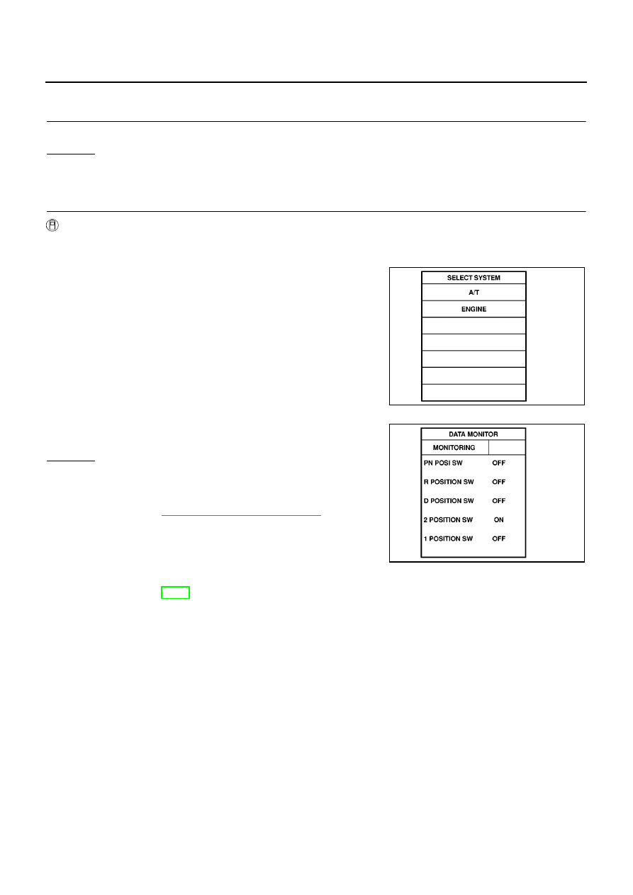
CHECK PNP SWITCH CIRCUIT (WITH CONSULT-II)

With CONSULT-II

1.

Turn ignition switch to “ON” position.
(Do not start engine.)

2.

Select “TCM INPUT SIGNALS” in “DATA MONITOR” mode for
“A/T” with CONSULT-II.

3.

Read out “P/N”, “R”, “D”, “2” and “1” position switches moving
selector lever to each position.

Check the signal of the selector lever position is indicated prop-
erly.

OK or NG

OK

>> GO TO 4

NG

>> Check the following items:

PNP switch
Refer to

AT-118, "Component Inspection"

.

Harness for short or open between ignition switch and
PNP switch (Main harness)

Harness for short or open between PNP switch and
TCM (Main harness)

Ignition switch and fuse
Refer to EL-11, “Power Supply Routing”.

Diode (P, N positions)

SAT014K

SAT701J

DTC P0705 PARK/NEUTRAL POSITION (PNP) SWITCH

AT-117

[EURO-OBD]

D

E

F

G

H

I

J

K

L

M

A

B

AT

3.

CHECK PNP SWITCH CIRCUIT (WITHOUT CONSULT-II)

Without CONSULT-II

1.

Turn ignition switch to “ON” position.
(Do not start engine.)

2.

Check voltage between TCM terminals 26, 27, 34, 35, 36 and ground while moving selector lever through
each position.

OK or NG

OK

>> GO TO 4

NG

>> Check the following items:

PNP switch
Refer to

AT-118, "Component Inspection"

.

Harness for short or open between ignition switch and PNP switch (Main harness)

Harness for short or open between PNP switch and TCM (Main harness)

Ignition switch and fuse
Refer to EL-11, “Power Supply Routing”.

Diode (P, N positions)

Voltage:

B: Battery voltage

0: 0V

MTBL0136

SCIA0753E

AT-118

[EURO-OBD]

DTC P0705 PARK/NEUTRAL POSITION (PNP) SWITCH

4.

CHECK DTC

Perform

AT-113, "DIAGNOSTIC TROUBLE CODE (DTC) CONFIRMATION PROCEDURE"

.

OK or NG

OK

>> INSPECTION END

NG

>> 1. Perform TCM input/output signal inspection.

2. If NG, recheck TCM pin terminals for damage or loose connection with harness connector.

Component Inspection

ECS0097E

PARK/NEUTRAL POSITION (PNP) SWITCH

1.

Check continuity between terminals 1 and 3 and between termi-
nals 2 and 4, 5, 6, 7, 8, 9 while moving manual shaft through
each position.

2.

If NG, check again with control cable disconnected from manual
shaft of A/T assembly. Refer to step 1.

3.

If OK on step 2, adjust control cable. Refer to

AT-412, "Control

Cable Adjustment"

.

4.

If NG on step 2, remove PNP switch from A/T and check conti-
nuity of PNP switch terminals. Refer to step 1.

5.

If OK on step 4, adjust PNP switch. Refer to

AT-412, "Park/Neu-

tral Position (PNP) Switch Adjustment"

.

6.

If NG on step 4, replace PNP switch.

Lever position

Terminal No.

P

3 — 7

1 — 2

R

3 — 8

N

3 — 9

1 — 2

D

3 — 6

2

3 — 5

1

3 — 4

MCIA0068E

SAT089JA

DTC P0710 A/T FLUID TEMPERATURE SENSOR CIRCUIT

AT-119

[EURO-OBD]

D

E

F

G

H

I

J

K

L

M

A

B

AT

DTC P0710 A/T FLUID TEMPERATURE SENSOR CIRCUIT

PFP:31940

Description

ECS0097F

The A/T fluid temperature sensor detects the A/T fluid temperature
and sends a signal to the TCM.

CONSULT-II REFERENCE VALUE IN DATA MONITOR MODE

Remarks: Specification data are reference values.

TCM TERMINALS AND REFERENCE VALUE

Remarks: Specification data are reference values.

ON BOARD DIAGNOSIS LOGIC

DIAGNOSTIC TROUBLE CODE (DTC) CONFIRMATION PROCEDURE

CAUTION:

Always drive vehicle at a safe speed.

NOTE:
If “DIAGNOSTIC TROUBLE CODE CONFIRMATION PROCEDURE” has been previously conducted,
always turn ignition switch “OFF” and wait at least 5 seconds before conducting the next test.

SCIA0735E

SAT021J

Monitor item

Condition

Specification (Approximately)

A/T fluid temperature sensor

Cold [20

°

C (68

°

F)]

Hot [80

°

C (176

°

F)]

1.5V

0.5V

2.5 k

0.3 k

Termi-

nal No.

Wire color

Item

Condition

Judgement stan-

dard

(Approx.)

42

B

Sensor ground

47

BR

A/T fluid tempera-
ture sensor

When ATF temperature is 20

°

C

(68

°

F).

1.5V

When ATF temperature is 80

°

C

(176

°

F).

0.5V

Diagnostic trouble code

Malfunction is detected when...

Check items (Possible cause)

: ATF TEMP SEN/CIRC

TCM receives an excessively low or high
voltage from the sensor.

Harness or connectors
(The sensor circuit is open or shorted.)

A/T fluid temperature sensor

: P0710


Content   ..  96  97  98  99   ..