Nissan Almera Tino V10. Manual - part 33


  Index      Nissan     Nissan Almera Tino V10 - Service Manual (2003 year)


Search            


Content   ..  31  32  33  34   ..


Nissan Almera Tino V10. Manual - part 33


strand will have a high resistance to the current. This will be picked
up as a slight voltage drop.
Unwanted resistance can be caused by many situations as follows:

I

Undersized wiring (single strand example)

I

Corrosion on switch contacts

I

Loose wire connections or splices.

If repairs are needed always use wire that is of the same or larger
gauge.
Measuring Voltage Drop — Accumulated Method
1)

Connect the voltmeter across the connector or part of the cir-
cuit you want to check. The positive lead of the voltmeter
should be closer to power and the negative lead closer to
ground.

2)

Operate the circuit.

3)

The voltmeter will indicate how many volts are being used to
“push” current through that part of the circuit.

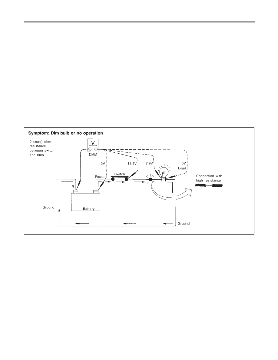
Note in the illustration that there is an excessive 4.1 volt drop
between the battery and the bulb.

SGI974

Measuring Voltage Drop — Step by Step
The step by step method is most useful for isolating excessive
drops in low voltage systems (such as those in “Computer Con-
trolled Systems”).
Circuits in the “Computer Controlled System” operate on very low
amperage.
The (Computer Controlled) system operations can be adversely
affected by any variation in resistance in the system. Such resis-
tance variation may be caused by poor connection, improper
installation, improper wire gauge or corrosion.
The step by step voltage drop test can identify a component or wire
with too much resistance.

HOW TO PERFORM EFFICIENT DIAGNOSES FOR AN ELECTRICAL INCIDENT

Circuit Inspection (Cont’d)

GI-28

SGI854

CONTROL UNIT CIRCUIT TEST

NLGI0005S0306

System Description: When the switch is ON, the control unit lights
up the lamp.

MGI034A

Input-output voltage chart

Pin No.

Item

Condition

Voltage
value V

In case of high resistance such as single strand V *

1

Switch

Switch ON

Battery voltage

Lower than battery voltage Approx. 8 (Example)

Switch OFF

Approx. 0

Approx. 0

2

Lamp

Switch ON

Battery voltage

Approx. 0 (Inoperative lamp)

Switch OFF

Approx. 0

Approx. 0

The voltage value is based on the body ground.
* : If high resistance exists in the switch side circuit (caused by a single strand), terminal 1 does not detect battery voltage. Control unit
does not detect the switch is ON even if the switch does not turn ON. Therefore, the control unit does not supply power to light up the
lamp.

MA

EM

LC

EC

FE

CL

MT

AT

AX

SU

BR

ST

RS

BT

HA

SC

EL

IDX

HOW TO PERFORM EFFICIENT DIAGNOSES FOR AN ELECTRICAL INCIDENT

Circuit Inspection (Cont’d)

GI-29

MGI035A

Input-output voltage chart

Pin No.

Item

Condition

Voltage
value V

In case of high resistance such as single strand V *

1

Lamp

Switch ON

Approx. 0

Battery voltage (Inoperative lamp)

Switch OFF

Battery voltage

Battery voltage

2

Switch

Switch ON

Approx. 0

Higher than 0 Approx. 4 (Example)

Switch OFF

Approx. 5

Approx. 5

The voltage value is based on the body ground.
* : If high resistance exists in the switch side circuit (caused by a single strand), terminal 2 does not detect approx. 0V. Control unit
does not detect the switch is ON even if the switch turns ON. Therefore, the control unit does not control ground to light up the lamp.

HOW TO PERFORM EFFICIENT DIAGNOSES FOR AN ELECTRICAL INCIDENT

Circuit Inspection (Cont’d)

GI-30

NLGI0006

NOTICE:
Trouble diagnoses indicate work procedures required to diagnose
incidents effectively. Observe the following instructions before diag-
nosing.
1)

Before performing trouble diagnoses, read the “Prelimi-
nary Check”, the “Symptom Chart” or the “Work Flow”.

2)

After repairs, re-check that the problem has been com-
pletely eliminated.

3)

Refer to Component Parts and Harness Connector Loca-
tion for the Systems described in each section for
identification/location of components and harness con-
nectors.

4)

Refer to the Circuit Diagram for quick pinpoint check.
If you need to check circuit continuity between harness
connectors in more detail, such as when a sub-harness is
used, refer to Wiring Diagram in each individual section
and Harness Layout in EL section for identification of har-
ness connectors.

5)

When checking circuit continuity, ignition switch should
be OFF.

6)

Before checking voltage at connectors, check battery volt-
age.

7)

After accomplishing the Diagnostic Procedures and Elec-
trical Components Inspection, make sure that all harness
connectors are reconnected as they were.

MA

EM

LC

EC

FE

CL

MT

AT

AX

SU

BR

ST

RS

BT

HA

SC

EL

IDX

HOW TO FOLLOW TROUBLE DIAGNOSES

GI-31


Content   ..  31  32  33  34   ..