Nissan Almera Tino V10. Manual - part 30
AGI070
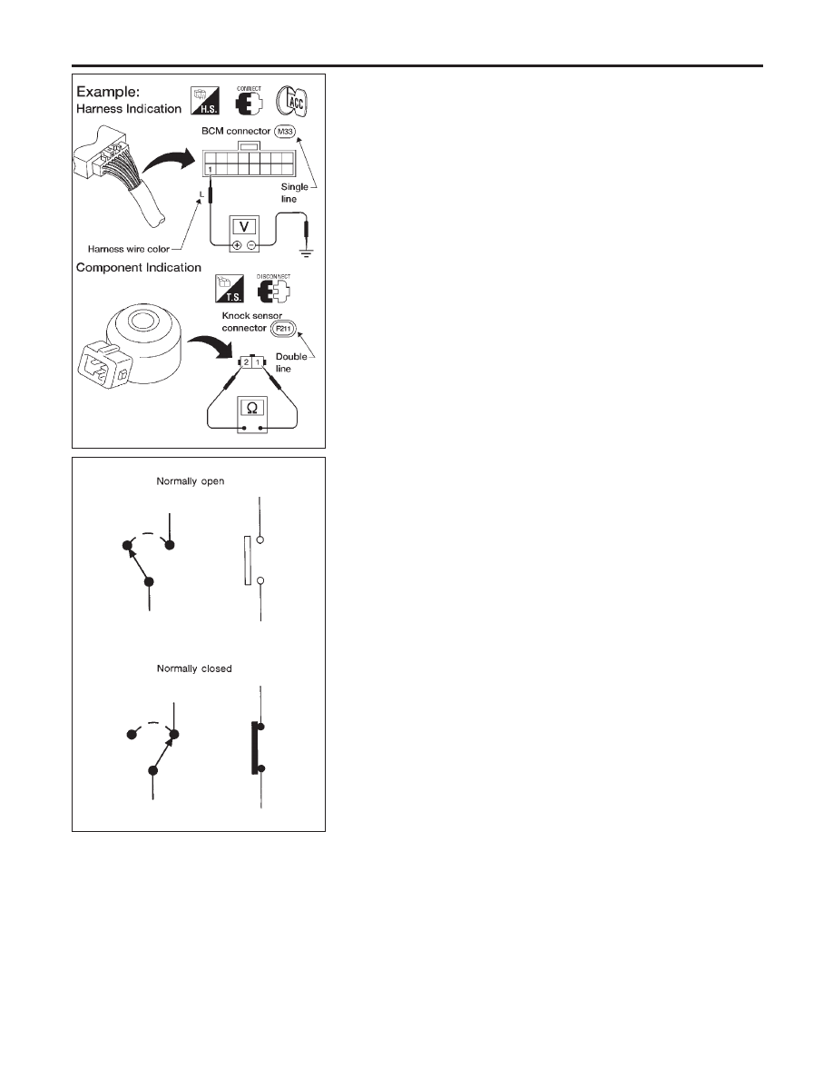
HARNESS INDICATION
NLGI0003S0202
I
Letter designations next to test meter probe indicate harness
(connector) wire color.
I
Connector numbers in a single circle M33 indicate harness
connectors.
COMPONENT INDICATION
NLGI0003S0203
I
Connector numbers in a double circle F211 indicate compo-
nent connectors.
SGI860
SWITCH POSITIONS
NLGI0003S0204
Switches are shown in wiring diagrams as if the vehicle is in the
“normal” condition.
A vehicle is in the “normal” condition when:
I
ignition switch is “OFF”,
I
doors, hood and trunk lid/back door are closed,
I
pedals are not depressed, and
I
parking brake is released.
HOW TO READ WIRING DIAGRAMS
Description (Cont’d)
GI-16