Nissan Almera Tino V10. Manual - part 29
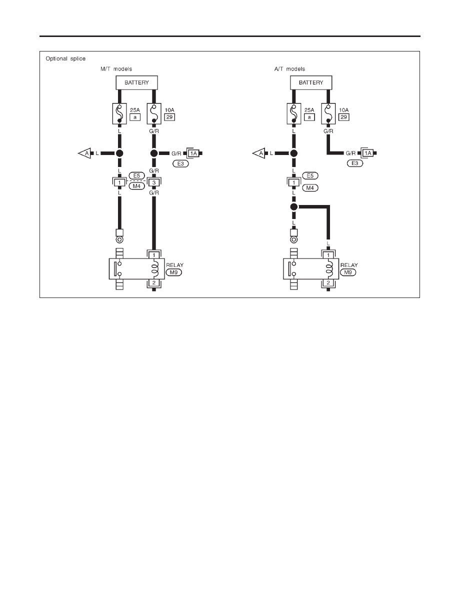
OPTIONAL SPLICE
NLGI0003S0101
SGI942
HOW TO READ WIRING DIAGRAMS
Sample/Wiring Diagram — EXAMPL — (Cont’d)
GI-12
|
|
|
OPTIONAL SPLICE NLGI0003S0101 SGI942 HOW TO READ WIRING DIAGRAMS Sample/Wiring Diagram — EXAMPL — (Cont’d) GI-12 |