Nissan Almera Tino V10. Manual - part 4
SFA612
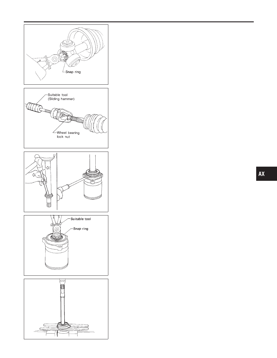
4.
Pry off snap ring, then remove spider assembly.
CAUTION:
Do not disassemble spider assembly.
5.
Draw out boot.
Cover drive shaft serration with tape to prevent damage to the
boot.
SFA092A
Wheel Side (ZF90, B90, AC2300I & AC3300I)
NLAX0017S02
1.
Before separating joint assembly, put matching marks on drive
shaft and joint assembly.
2.
Separate joint assembly with a suitable tool.
Be careful not to damage threads on drive shaft.
3.
Remove boot bands.
4.
Draw out boot.
SFA442B
Support Bearing
NLAX0017S03
1.
Remove dust shield.
SFA692
2.
Remove snap ring.
SFA693
3.
Press support bearing assembly off of drive shaft.
GI
MA
EM
LC
EC
FE
CL
MT
AT
SU
BR
ST
RS
BT
HA
SC
EL
IDX
FRONT AXLE
Drive Shaft (Cont’d)
AX-13