Nissan Almera Tino V10. Manual - part 3
SFA182A
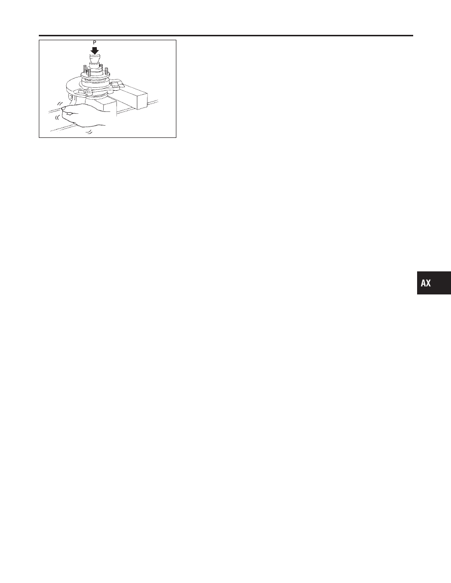
5.
Check bearing operation.
a.
Add load P with press.
Load P:
49.0 kN
(5.0 ton, 5.5 US ton, 4.92 Imp ton)
b.
Spin knuckle several turns in both directions.
c.
Make sure that wheel bearings operate smoothly.
GI
MA
EM
LC
EC
FE
CL
MT
AT
SU
BR
ST
RS
BT
HA
SC
EL
IDX
FRONT AXLE
Wheel Hub and Knuckle (Cont’d)
AX-9