содержание .. 312 313 314 315 ..
Nissan GT-R. Manual - part 314
VTL-12
< REMOVAL AND INSTALLATION >
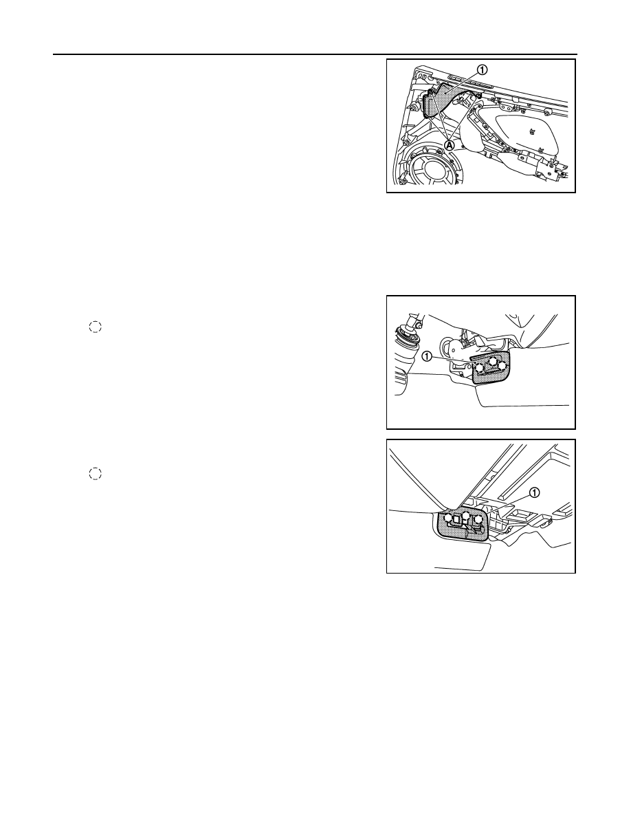
DUCT AND GRILLE
2.
Remove mounting screws (A), and then remove side defroster
duct RH (1).
INSTALLATION
Installation is basically the reverse order of removal.
FOOT GRILLE
FOOT GRILLE : Removal and Installation
INFOID:0000000009160148
REMOVAL
1.
Remove foot grille LH (1).
2.
Remove foot grille RH (1).
INSTALLATION
Installation is basically the reverse order of removal.
HEATER DUCT
HEATER DUCT : Removal and Installation
INFOID:0000000009160149
REMOVAL
NNIIA0093ZZ
: Pawl
JSIIA1249ZZ
: Pawl
JSIIA1250ZZ