содержание .. 307 308 309 310 ..
Nissan GT-R. Manual - part 309
SHIFT POSITION
TM-15
< PERIODIC MAINTENANCE >
[TRANSMISSION: GR6Z30A]
C
E
F
G
H
I
J
K
L
M
A
B
TM
N
O
P
SHIFT POSITION
Inspection and Adjustment
INFOID:0000000009162744
INSPECTION
1.
Turn the ignition switch to ON at the shift lever P position.
2.
The shift lever can shift from the P position to the R position when the brake pedal is depressed. Alterna-
tively, the shift lever cannot shift from the P position to the R position without the brake pedal depressed.
3.
Operate the shift lever and check for excessive effort, sticking, noise or rattle.
4.
When the shift lever is operated, a click is felt, and the fixed position is correct and corresponds to the shift
position indicator in the combination meter
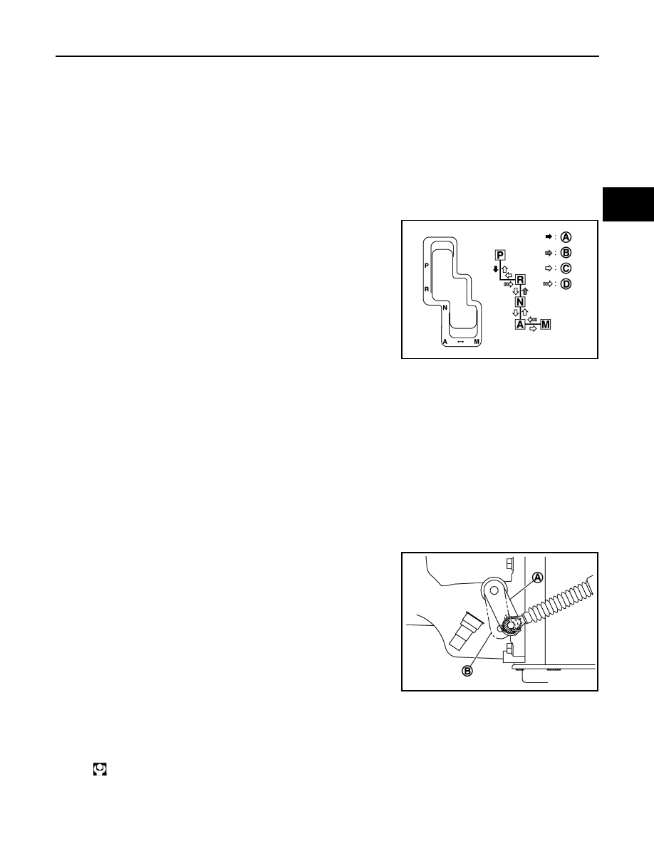
5.
Check that the shift lever is shifted through all the shift positions
in the manner shown in the figure.
6.
Check in the P and N positions that the knob button can be
operated without sticking when the button is pressed without the
shift lever pressed forward and backward.
7.
Check that in the R position the shift lever can be operated with-
out sticking when the shift lever is operated left and right.
8.
The back-up lamp can turn on and the reverse warning buzzer can sound with the shift lever in the R posi-
tion only.
9.
Check that the engine can be started with the shift lever in the P and N positions only.
10. The transmission is completely locked with the shift lever in the P position.
11. The shift position indicator of combination meter should change to the A range display or M range display
when the shift lever is operated to the M position.
12. The shift position indicator in the combination meter should not change when each load of 30 N (3.1 kg) is
applied (pressed) to front and rear side at the shift lever in the P position, front side at the shift lever in the
R position, front side at the shift lever in the N position and rear side at the shift lever in the A position.
ADJUSTMENT
1.
Disconnect the control cable from the A/T shift selector assembly.
2.
Shift the parking lever of transmission assembly to the P range
(A).
3.
Rotate the wheels at least a quarter turn and the Park position
mechanism is fully engaged.
4.
Shift the shift lever to the P position.
5.
Install the socket of the control cable to the A/T shift selector
assembly, and fix them with lock plate.
6.
Insert the I-end bolt into the cable lever of the A/T shift selector
assembly, and apply the load of 9.8 N (1 kg) in the cable lever P
direction (toward vehicle front) to the control cable.
7.
Release the control cable and temporarily tighten the lock nut. Then, tighten the lock nut to the specified
torque.
A
: Depress the brake pedal. Press and operate the knob button.
B
: Press and operate the knob button.
C
: Operate without condition.
D
: Automatic return.
NNDIA0020JP
B
: Other than P position
:14.7 N·m (1.5 kg-m, 11 ft-lb)
NNDIA0011ZZ