содержание .. 254 255 256 257 ..
Nissan GT-R. Manual - part 256
RSU-14
< SERVICE DATA AND SPECIFICATIONS (SDS)
SERVICE DATA AND SPECIFICATIONS (SDS)
SERVICE DATA AND SPECIFICATIONS (SDS)
SERVICE DATA AND SPECIFICATIONS (SDS)
EXCEPT TRACK PACK-SPECIFIC SUSPENSION
EXCEPT TRACK PACK-SPECIFIC SUSPENSION : Wheel Alignment
INFOID:0000000009163956
CAUTION:
• This work is recommended to be performed by GT-R certified NISSAN dealer.
• Adjust wheel alignment with the vehicle in customer's regular use condition (e.g. normal stock
items), with the fuel in full-tank condition, and with no one in the vehicle.
• To adjust wheel alignment, set tire pressure at 250 kPa (2.5 kg/cm
2
, 36 psi). After adjusting wheel
alignment, adjust tire pressure to the specified value. Refer to
.
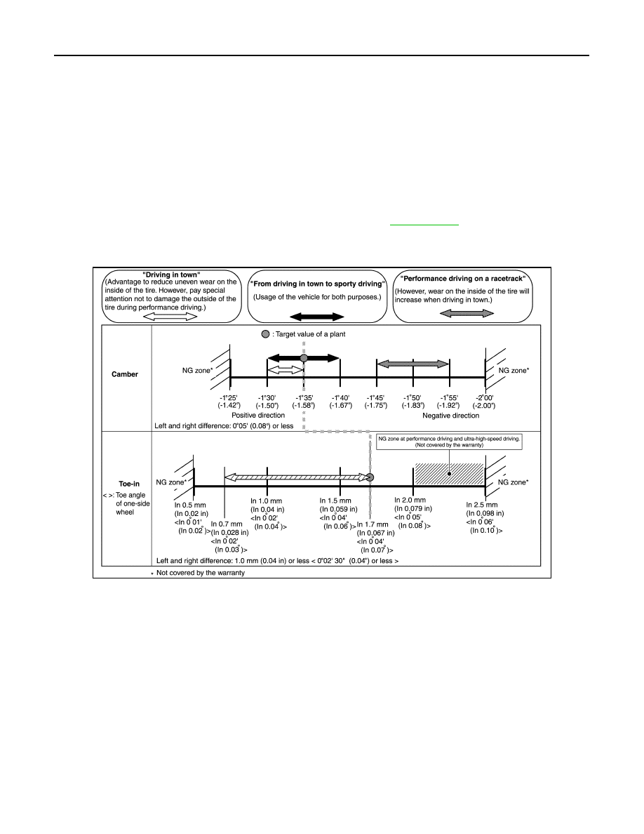
CAMBER, TOE-IN
Setting guide depending on the customer’s driving
• Adjust wheel alignment to the customer’s driving style.
• Never set to toe-out.
- Always adjust to toe-in. If the wheels change to toe-out, tire partial wear is accelerated and local heating may
be accelerated in the inner side of tires.
- For the above reasons, always adjust to toe-in for the vehicle of a customer who drives on a racetrack.
- Engaging in performance driving on a racetrack and ultra-high-speed driving, be sure to adjust toe-in to 2.0
mm (0.079 in) or less. If used beyond this range, it is not covered by the warranty.
• When driving on a racetrack, recommend to adjust the alignment to the “Performance driving on a racetrack”
setting. If the negative camber angle is insufficient driving on a technical course including many tight turns
may result in wear on the outside of the tire and this can cause an accident. [To avoid uneven wear, servicing
the vehicle after performance driving (at the customer's expense) is recommended to result the alignment to
the original setting.]
• Wheel alignment can be changed in process of time and mileage, as suspension parts do not adjust to each
other up to the mileage of about 1,000 miles or 2,000 km.
• Remarks for up to the mileage of 1,000 miles or 2,000 km
- Toe angle of one-side wheel: See reference value.
TRACK PACK-SPECIFIC SUSPENSION
JSEIA0487GB