Nissan GT-R. Manual - part 150


  Главная      Nissan     Nissan GT-R (2007-2014 year) - Service Manual


поиск по сайту            


содержание   ..  148  149  150  151   ..


Nissan GT-R. Manual - part 150


DOOR GLASS

GW-23

< REMOVAL AND INSTALLATION >

C

D

E

F

G

H

I

J

L

M

A

B

GW

N

O

P

DOOR GLASS

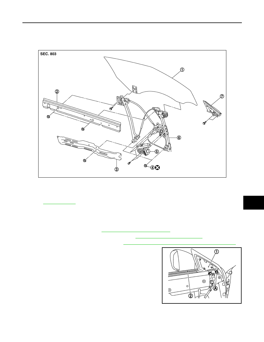
Exploded View (GT-R certified NISSAN dealer)

INFOID:0000000009161687

Removal and Installation (GT-R certified NISSAN dealer)

INFOID:0000000009161688

REMOVAL

1.

Remove the door finisher. Refer to 

INT-12, "Removal and Installation"

2.

Disconnect the tweeter harness connector. Refer to 

AV-81, "Removal and Installation"

3.

Remove the door corner cover inner. Refer to 

MIR-16, "DOOR MIRROR ASSEMBLY : Exploded View"

.

4.

Remove the corner piece mounting bolts (A), and then remove
the corner piece (1) and the door inner seal (2). 

1.    Door glass assembly

2.

Door inner reinforcement

3.

Door module base

4.

Nut

5.

Power window motor

6.

Regulator assembly

7.

Corner piece assembly

Refer to 

GI-4, "Components"

 for symbols in the figure.

JMKIA2790ZZ

JMKIA2792ZZ

GW-24

< REMOVAL AND INSTALLATION >

DOOR GLASS

5.

Remove the sealing screen (1). 
NOTE:
Cut butyl tape using a cutter knife so that tape remains on the
sealing screen if the screen is reused. 

6.

Operate the power window switch to raise/lower the door glass
until the glass bolts can be seen. 
NOTE:
Connect the harness connector to the power window switch. 

7.

Loosen the door glass mounting bolt (A), and then remove the
mounting bolt (B). 

8.

Pull the door glass (1) from the door panel while lifting it up over
the door glass rear edge. 

INSTALLATION

Install in the reverse order of removal.
NOTE:
Always perform the glass position adjustment. 

Inspection and adjustment (GT-R certified NISSAN dealer)

INFOID:0000000009161689

SYSTEM INITIALIZATION

Perform system initialization if the following operation is performed. 
• When disconnecting the battery cable and when the power supplied to the power window motor and motor is

cut off by blowout of power fuse 

• Removal and installation of regulator assembly
• Removal and installation of motor from regulator assembly
• Removal and installation of power window switch harness connector 
• Operation of regulator assembly as an independent unit
• Removal and installation of glass
• Removal and installation of door weather-strip

Initial Setting

After installing each component, follow the steps below:
1.

Disconnect the battery negative terminal or power window main switch connector. Reconnect it after wait-
ing a minute or more. 

2.

Close the door. 

JMKIA2791ZZ

JMKIA2793ZZ

JMKIA2794ZZ

DOOR GLASS

GW-25

< REMOVAL AND INSTALLATION >

C

D

E

F

G

H

I

J

L

M

A

B

GW

N

O

P

3.

Turn the ignition switch ON.

4.

Operate the power window switch to fully open the glass. (This operation is unnecessary if the glass is
already fully open)

5.

Pull the power window switch UP (AUTO UP position). Even after the glass stops at the fully closed posi-
tion, continue pulling the switch for 2 seconds or more. 

6.

Inspect anti-pinch function. 
NOTE:
If the open/close operation is repeated continuously, the initial setting may be cancelled. Perform the initial
setting in that situation. 

CHECK ANTI-PINCH FUNCTION

1.

Open the door glass fully.

2.

Place a piece of wood (e.g., handle of wooden hammer) near the fully closed position. 

3.

Close the door glass fully with AUTO UP. 
• Check that the glass lowers approximately 150 mm after contacting the piece of wood and then stops. 
• Check that the glass does not rise when operating the power window main switch while lowering. 

CAUTION:

• Be careful not to be pinched
• Check that the auto up function is normal before inspection following the system initialization

FITTING INSPECTION

1.

Check that the overlap length with the body side weather-strip is maintained on the glass securely. 

2.

Check that the clearance with the side window is parallel when the glass is closed. If the clearance
between glass and side window is not parallel, loosen the mounting nut of glass and carrier plate and cor-
rect the glass position. 

3.

Check for any operation that is not normal while raising and lowering the glass. 

GLASS POSITION ADJUSTMENT

1.

Raise glass to the fully closed position. 

2.

Rotate the adjustment nuts (a), (b), or (c) aligning with the upper side of glass and the body side weather-
strip to adjustment. 

NOTE:
• Basically perform the adjustment using the adjustment nut (a). Perform the adjustment using the adjust-

ment nut (b) or (c) if the glass position is not adjusted correctly using the adjustment nut (a). 

• Rotate the adjustment nut clockwise to move the door glass upper edge to the outside. 

1.

Door glass assembly

2.

Body side weather-strip

3.

Body side welt (front)

4.

Front pillar finisher

5.

Front pillar outer

6.

Front pillar inner

7.

Roof side inner rail

8.

Side window glass

9.

Rear fender

NNKIA0014GB

GW-26

< REMOVAL AND INSTALLATION >

DOOR GLASS

• Rotate the adjustment nut counterclockwise to move the door glass upper edge to the inside. 
• Be careful that the adjustment procedure for the adjustment nut (c) is opposite in the procedure for the

adjustment nut (a) or (b). 


содержание   ..  148  149  150  151   ..