Nissan GT-R. Manual - part 151


  Главная      Nissan     Nissan GT-R (2007-2014 year) - Service Manual


поиск по сайту            


содержание   ..  149  150  151  152   ..


Nissan GT-R. Manual - part 151


DOOR REGULATOR

GW-27

< REMOVAL AND INSTALLATION >

C

D

E

F

G

H

I

J

L

M

A

B

GW

N

O

P

DOOR REGULATOR

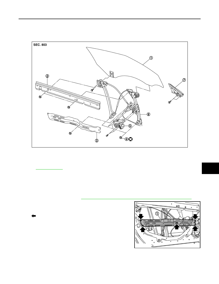
Exploded View (GT-R certified NISSAN dealer)

INFOID:0000000009161690

Removal and Installation (GT-R certified NISSAN dealer)

INFOID:0000000009161691

REGULATOR ASSEMBLY

Removal

1.

Remove the door glass. Refer to 

GW-23, "Removal and Installation (GT-R certified NISSAN dealer)"

.

2.

Remove the mounting nuts and bolts, and then remove the door
module base (1). 

1.    Door glass assembly

2.

Door inner reinforcement

3.

Door module base

4.

Nut

5.

Power window motor

6.

Regulator assembly

7.

Corner piece assembly

Refer to 

GI-4, "Components"

 for symbols in the figure.

JMKIA2790ZZ

: Bolt

JMKIA2796ZZ

GW-28

< REMOVAL AND INSTALLATION >

DOOR REGULATOR

3.

Disconnect the power window motor harness connector (A). 

4.

Remove the door finisher bracket (1) using a socket wrench (A). 

5.

Remove the regulator assembly mounting nut using a socket
wrench, and then remove the regulator assembly. 

Installation

Install in the reverse order of removal.
NOTE:
Always perform the glass position adjustment. 

CAUTION:

The regulator assembly mounting nuts (bottom side) can not be reused. Replace them by new nuts.

Inspection After Removal

Check regulator assembly for the following item. Replace if neces-
sary. 
• Wire wear
• Deformation of regulator assembly

Disassembly and assembly (GT-R certified NISSAN dealer)

INFOID:0000000009161692

DISASSEMBLY

1.

Remove the regulator assembly from the door panel. 

JMKIA2797ZZ

JMKIA2795ZZ

: Nut

JMKIA2798ZZ

JMKIA2799ZZ

DOOR REGULATOR

GW-29

< REMOVAL AND INSTALLATION >

C

D

E

F

G

H

I

J

L

M

A

B

GW

N

O

P

2.

Remove the power window motor from the regulator assembly. 

ASSEMBLY

Assembly is the reverse order of disassembly.

Inspection and adjustment (GT-R certified NISSAN dealer)

INFOID:0000000009161693

SYSTEM INITIALIZATION

Perform system initialization if the following operation is performed. 
• When disconnecting the battery cable and when the power supplied to the power window motor and motor is

cut off by blowout of power fuse 

• Removal and installation of regulator assembly
• Removal and installation of motor from regulator assembly
• Removal and installation of power window switch harness connector 
• Operation of regulator assembly as an independent unit
• Removal and installation of glass
• Removal and installation of door weather-strip

Initial Setting

After installing each component, follow the steps below:
1.

Disconnect the battery negative terminal or power window main switch connector. Reconnect it after wait-
ing a minute or more. 

2.

Close the door. 

3.

Turn the ignition switch ON.

4.

Operate the power window switch to fully open the glass. (This operation is unnecessary if the glass is
already fully open)

5.

Pull the power window switch UP (AUTO UP position). Keep pulling the switch for 2 seconds or more
even after glass stops at the fully closed position. 

6.

Inspect anti-pinch function. 
NOTE:
If the open/close operation is repeated continuously, the initial setting may be cancelled. Perform the initial
setting in that situation. 

CHECK ANTI-PINCH FUNCTION

1.

Open the door glass fully.

2.

Place a piece of wood (e.g., handle of wooden hammer) near the fully closed position. 

3.

Close the door glass fully with AUTO UP. 
• Check that the glass lowers approximately 150 mm(5.906 in) after contacting the piece of wood and

then stops. 
However, when the objects of more than 60 mm(2.362 in) are pinched, it is lowered approximately 100
mm(3.937 in), and then it may stop. 

• Check that the glass does not rise when operating the power window main switch while lowering. 

CAUTION:

• Be careful not to be pinched
• Check that the auto up function is normal before the inspection following the system initializa-

tion

FITTING INSPECTION

1.

Check that the overlap length with the body side weather-strip is maintained on the glass securely. 

2.

Check that the clearance with the side window is parallel when the glass is closed. If the clearance
between glass and side window is not parallel, loosen the mounting nut of glass and carrier plate and cor-
rect the glass position. 

3.

Check for any unusual operation while raising and lowering the glass. 

GLASS POSITION ADJUSTMENT

1.

Raise glass to the fully closed position. 

2.

Rotate the adjustment nuts (a), (b), or (c) aligning with the upper side of glass and the body side weather-
strip to adjustment. 

GW-30

< REMOVAL AND INSTALLATION >

DOOR REGULATOR

NOTE:
• Basically perform the adjustment using the adjustment nut (a). Perform the adjustment using the adjust-

ment nut (b) or (c) if the glass position is not adjusted correctly using the adjustment nut (a). 

• Rotate the adjustment nut clockwise to move the door glass upper edge to the outside. 
• Rotate the adjustment nut counterclockwise to move the door glass upper edge to the inside. 
• Be careful that the adjustment procedure for the adjustment nut (c) is opposite in the procedure for the

adjustment nut (a) or (b). 

1.

Door glass assembly

2.

Body side weather-strip

3.

Body side welt (front)

4.

Front pillar finisher

5.

Front pillar outer

6.

Front pillar inner

7.

Roof side inner rail

8.

Side window glass

9.

Rear fender

NNKIA0014GB


содержание   ..  149  150  151  152   ..