Nissan Pathfinder (2012 year). Manual - part 518


  Index      Manuals     Nissan Pathfinder (2012 year) - Service and Repair Manual


Search            copyright infringement  


Content      ..     516      517      518      519     ..


Nissan Pathfinder (2012 year). Manual - part 518


REAR SUSPENSION MEMBER

RSU-21

< UNIT REMOVAL AND INSTALLATION >

C

D

F

G

H

I

J

K

L

M

A

B

RSU

N

O

P

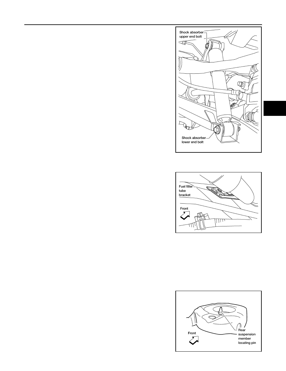
14. Set a suitable jack under each front lower link for support and

remove the shock absorber upper end bolts and lower end bolts

using power tool.

15. Remove both of the shock absorbers.

16. Set a suitable jack under the rear suspension member.
17. Remove the six rear suspension member bolts using power tool.
18. Slowly lower the jack supporting the rear suspension member to

access the fuel filler tube bracket, then remove the two bolts to

disconnect the fuel filler tube bracket from the rear suspension

member. 

19. Slowly lower the jack to remove the rear suspension member, suspension arm, front and rear lower links,

knuckles, and stabilizer bar as an assembly.

20. Remove the suspension arm, spare tire bracket, stabilizer bar, front and rear lower links, and the knuckles

from the rear suspension member using power tool.

INSPECTION AFTER REMOVAL

Check rear suspension member for deformation, cracks, and other damage and replace if necessary.

INSTALLATION

Installation is in the reverse order of removal.

• When raising the rear suspension member assembly, use the

locating pins to align the rear suspension member to the vehicle

body.

LEIA0110E

LEIA0114E

LEIA0083E

August 2012

2012 Pathfinder

RSU-22

< UNIT REMOVAL AND INSTALLATION >

REAR SUSPENSION MEMBER

• When installing the upper and lower rubber seats for the rear coil

springs, the arrow embossed on the rubber seats must point out

toward the wheel and tire assembly.

• Perform final tightening of the nuts and bolts for the links (with rubber bushings) under unladen conditions

with the tires on level ground.

• Adjust the parking brake cables. Refer to 

PB-5, "On-Vehicle Service"

.

• Check the wheel alignment. Refer to 

FSU-7, "Front Wheel Alignment"

.

LEIA0076E

August 2012

2012 Pathfinder

SERVICE DATA AND SPECIFICATIONS (SDS)

RSU-23

< SERVICE DATA AND SPECIFICATIONS (SDS) 

C

D

F

G

H

I

J

K

L

M

A

B

RSU

N

O

P

SERVICE DATA AND SPECIFICATIONS (SDS)

SERVICE DATA AND SPECIFICATIONS (SDS)

Wheel Alignment (Unladen*)

INFOID:0000000007357029

*1: Fuel, radiator coolant and engine oil full. Spare tire, jack, hand tools and mats in designed positions. 

Ball Joint

INFOID:0000000007357030

*: Measurement point is at the bolt groove of the ball stud.

Camber
Degree minute (decimal degree)

Minimum

- 0

°

 32

 (- 0.53

°

)

Nominal

- 0

°

 2

 (- 0.03

°

)

Maximum

0

°

 28

 (0.47

°

)

Toe-in

Distance

Minimum

Out 1.4 mm (Out 0.05 in)

Nominal

In 1.9 mm (In 0.07 in)

Maximum

In 5.2 mm (In 0.20 in)

Angle
Degree minute (decimal degree)

Minimum

Out 0

°

 3' 36

 (Out 0.06

°

)

Nominal

In 0

°

 8' 24

 (In 0.14

°

)

Maximum

In 0

°

 20' 24

 (In 0.34

°

)

Ball joint position

Upper

Lower

Swinging force* (A)

11.4 - 145.5 N (1.16 - 14.8 kg, 2.56 - 32.7 lb)

11.0 - 140.7 N (1.12 - 14.35 kg, 2.47 - 31.63 lb)

Turning torque (B)

0.5 - 6.4 N·m (0.06 - 0.65 kg-m, 5 - 56 in-lb)

0.5 - 6.4 N·m (0.06 - 0.65 kg-m, 5 - 56 in-lb)

Vertical end play (C)

0 mm (0 in)

0 mm (0 in)

Height (D)

44 mm (1.73 in)

45.5 mm (1.79 in)

WEIA0131E

August 2012

2012 Pathfinder

RSU-24

< SERVICE DATA AND SPECIFICATIONS (SDS) 

SERVICE DATA AND SPECIFICATIONS (SDS)

Wheelarch Height (Unladen*)

INFOID:0000000007357031

Unit: mm (in)

*1: Fuel, radiator coolant and engine oil full. Spare tire, jack, hand tools and mats in designated positions.

Engine

VQ40DE

VK56DE

Drive type

2WD

4WD

4WD

Tire size

P245/75R16

P265/65R17

P265/60R18

P245/75R16

P265/65R17 P265/60R18

P265/60R18

Front wheelarch height 
(Hf)

867

(34.13)

865 

(34.06)

867

(34.13)

875

(34.45)

874

(34.41)

891

(35.08)

876

(34.49)

Rear wheelarch height 
(Hr)

875

(34.45)

873

(34.37)

875

(34.45)

884

(34.80)

883

(34.76)

901

(35.47)

886

(34.88)

LEIA0085E

August 2012

2012 Pathfinder

SB-2

< PRECAUTION >

PRECAUTIONS

PRECAUTION

PRECAUTIONS

Precaution for Supplemental Restraint System (SRS) "AIR BAG" and "SEAT BELT 
PRE-TENSIONER"

INFOID:0000000007356462

The Supplemental Restraint System such as “AIR BAG” and “SEAT BELT PRE-TENSIONER”, used along

with a front seat belt, helps to reduce the risk or severity of injury to the driver and front passenger for certain

types of collision. This system includes seat belt switch inputs and dual stage front air bag modules. The SRS

system uses the seat belt switches to determine the front air bag deployment, and may only deploy one front

air bag, depending on the severity of a collision and whether the front occupants are belted or unbelted.

Information necessary to service the system safely is included in the SR and SB section of this Service Man-

ual.

WARNING:

• To avoid rendering the SRS inoperative, which could increase the risk of personal injury or death in

the event of a collision which would result in air bag inflation, all maintenance must be performed by

an authorized NISSAN/INFINITI dealer.

• Improper maintenance, including incorrect removal and installation of the SRS, can lead to personal

injury caused by unintentional activation of the system. For removal of Spiral Cable and Air Bag

Module, see the SR section.

• Do not use electrical test equipment on any circuit related to the SRS unless instructed to in this

Service Manual. SRS wiring harnesses can be identified by yellow and/or orange harnesses or har-

ness connectors.

PRECAUTIONS WHEN USING POWER TOOLS (AIR OR ELECTRIC) AND HAMMERS

WARNING:

• When working near the Airbag Diagnosis Sensor Unit or other Airbag System sensors with the Igni-

tion ON or engine running, DO NOT use air or electric power tools or strike near the sensor(s) with a

hammer. Heavy vibration could activate the sensor(s) and deploy the air bag(s), possibly causing

serious injury.

• When using air or electric power tools or hammers, always switch the Ignition OFF, disconnect the

battery, and wait at least 3 minutes before performing any service.

Precaution Necessary for Steering Wheel Rotation After Battery Disconnect

INFOID:0000000007356464

NOTE:

• This Procedure is applied only to models with Intelligent Key system and NATS (NISSAN ANTI-THEFT SYS-

TEM).

• Remove and install all control units after disconnecting both battery cables with the ignition knob in the

LOCK

 position.

• Always use CONSULT to perform self-diagnosis as a part of each function inspection after finishing work. If

DTC is detected, perform trouble diagnosis according to self-diagnostic results.

For models equipped with the Intelligent Key system and NATS, an electrically controlled steering lock mech-

anism is adopted on the key cylinder.

For this reason, if the battery is disconnected or if the battery is discharged, the steering wheel will lock and

steering wheel rotation will become impossible.

If steering wheel rotation is required when battery power is interrupted, follow the procedure below before

starting the repair operation.

OPERATION PROCEDURE

1. Connect both battery cables.

NOTE:

Supply power using jumper cables if battery is discharged.

2. Use the Intelligent Key or mechanical key to turn the ignition switch to the 

ACC

 position. At this time, the

steering lock will be released.

3. Disconnect both battery cables. The steering lock will remain released and the steering wheel can be

rotated.

4. Perform the necessary repair operation.

August 2012

2012 Pathfinder

PRECAUTIONS

SB-3

< PRECAUTION >

C

D

E

F

G

I

J

K

L

M

A

B

SB

N

O

P

5. When the repair work is completed, return the ignition switch to the 

LOCK

 position before connecting

the battery cables. (At this time, the steering lock mechanism will engage.)

6. Perform a self-diagnosis check of all control units using CONSULT. 

Precaution for Seat Belt Service

INFOID:0000000007356463

CAUTION:

• Before removing the seat belt pre-tensioner assembly, turn the ignition switch OFF, disconnect both

battery cables and wait at least 3 minutes.

• After replacing or reinstalling seat belt pre-tensioner assembly, or reconnecting seat belt pre-ten-

sioner assembly connector, ensure entire SRS operates properly. Refer to 

SRC-13, "SRS Operation

Check"

.

• Do not disassemble buckle or seat belt assembly.

• Do not reuse seat belt anchor bolts after removal. Replace with new ones.

• Replace anchor bolts if they are deformed or worn out.

• Never oil tongue and buckle.

• If any component of seat belt assembly is questionable, do not repair. Replace the whole seat belt

assembly.

• If webbing is cut, frayed, or damaged, replace seat belt assembly.

• When replacing seat belt assembly, use a genuine NISSAN seat belt assembly.

AFTER A COLLISION

WARNING:

• Inspect all seat belt assemblies including retractors and attaching hardware after any collision.

• NISSAN recommends that all seat belt assemblies in use during a collision be replaced unless the

collision was minor and the belts show no damage and continue to operate properly. Failure to do so

could result in serious personal injury in an accident. Seat belt assemblies not in use during a colli-

sion should also be replaced if either damage or improper operation is noted. Seat belt pre-tensioner

should be replaced even if the seat belts are not in use during a frontal collision in which the air bags

are deployed.

Replace any seat belt assembly (including anchor bolts) if:

• The seat belt was in use at the time of a collision (except for minor collisions and the belts, retractors and

buckles show no damage and continue to operate properly).

• The seat belt was damaged in an accident. (i.e., torn webbing, bent retractor or guide, etc.)

• The seat belt attaching point was damaged in an accident. Inspect the seat belt attaching area for damage

or distortion and repair as necessary before installing a new seat belt assembly.

• Anchor bolts are deformed or worn out.

• The seat belt pre-tensioner should be replaced even if the seat belts are not in use during the collision in

which the air bags are deployed.

August 2012

2012 Pathfinder

SB-4

< REMOVAL AND INSTALLATION >

SEAT BELTS

REMOVAL AND INSTALLATION

SEAT BELTS

Removal and Installation of Front Seat Belt

INFOID:0000000007356465

REMOVAL OF SEAT BELT RETRACTOR 

CAUTION:

• Before servicing SRS, turn the ignition switch off, disconnect both battery terminals and wait at least

three minutes.

1. Disconnect the negative and positive battery terminals, then wait at least three minutes.
2. Remove the center pillar upper and lower finishers. Refer to 

INT-19, "Removal and Installation"

.

3. Remove anchor cover and seat belt lower anchor bolt.
4. Remove the retractor anchor bolt, retractor bolt upper, then remove the retractor and belt assembly. 

• On RH side, disconnect the seat belt tension sensor.

5. Disconnect the seat belt pre-tensioner harness connector.

CAUTION:

1.

Center pillar upper finisher

2.

 D-ring anchor

3.

 D-ring anchor bolt cover

4.

Seat belt retractor and belt assembly 
RH

5.

Seat belt lower anchor RH 
(seat belt tension sensor)

6.

Seat belt tension sensor connector

7.

Anchor cover RH

8.

Anchor cover LH

9.

Seat belt lower anchor LH

10. Center pillar lower finisher

11. Seat belt pre-tensioner 

connector

12. Seat belt retractor and belt assembly LH

13. Center pillar

14. Seat belt height adjuster

A.

Height adjuster anchor bolt

B.

D-ring anchor bolt

C.

Seat belt lower anchor bolt  D.

Retractor anchor bolt

E.

Retractor bolt upper

Vehicle front

WHIA0344E

August 2012

2012 Pathfinder


Content      ..     516      517      518      519     ..