Nissan Pathfinder (2012 year). Manual - part 516


  Index      Manuals     Nissan Pathfinder (2012 year) - Service and Repair Manual


Search            copyright infringement  


Content      ..     514      515      516      517     ..


Nissan Pathfinder (2012 year). Manual - part 516


NOISE, VIBRATION, AND HARSHNESS (NVH) TROUBLESHOOTING

RSU-5

< SYMPTOM DIAGNOSIS >

C

D

F

G

H

I

J

K

L

M

A

B

RSU

N

O

P

SYMPTOM DIAGNOSIS

NOISE, VIBRATION, AND HARSHNESS (NVH) TROUBLESHOOTING

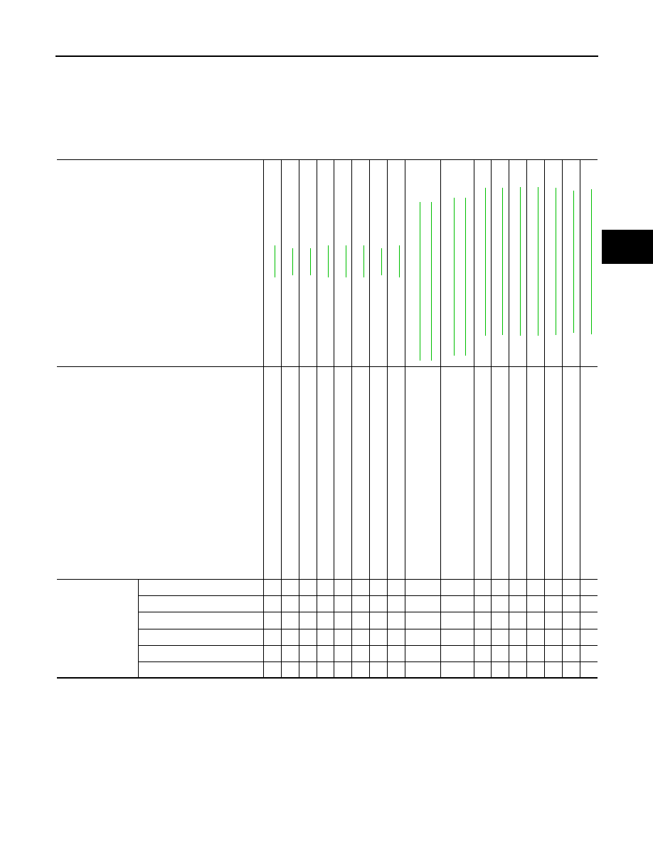
NVH Troubleshooting Chart

INFOID:0000000007357017

Use chart below to help you find the cause of the symptom. If necessary, repair or replace these parts.

×

: Applicable

Reference page

RSU-10

RSU-9

RSU-6

RSU-10

RSU-24

RSU-10

RSU-6

RSU-18

DL

N-32

7,

 "NVH T

rou

bl

es

ho

ot

in

g Cha

rt"

 (2S

13

30)

DL

N-33

8,

 "NVH T

rou

bl

es

ho

ot

in

g Cha

rt"

 (2S

13

50)

DL

N-41

8, 

"NVH T

ro

ubl

es

ho

ot

ing

 Cha

rt"

 (R

20

0)

DL

N-45

5, 

"NVH T

ro

ubl

es

ho

ot

ing

 Cha

rt"

 (R

23

0)

FS

U-6, 

"NVH T

rou

bl

es

ho

oti

ng

 Cha

rt"

FA

X-5,

 "NVH T

ro

ub

les

ho

ot

ing

 Ch

art"

W

T-4

8, "

N

V

H

 T

rou

bl

es

ho

oti

ng

 Cha

rt"

W

T-4

8, "

N

V

H

 T

rou

bl

es

ho

oti

ng

 Cha

rt"

FA

X-5,

 "NVH T

ro

ub

les

ho

ot

ing

 Ch

art"

B

R

-6

, "

N

V

H

 T

rou

bl

es

ho

oti

ng

 Cha

rt"

ST

-1

1, 

"NVH T

ro

ubl

es

ho

ot

ing

 Cha

rt"

Possible cause and SUSPECTED PARTS

Imp

rop

er i

ns

ta

lla

tio

n,

 lo

os

en

es

s

Sh

oc

k abs

o

rber de

form

at

io

n, 

d

am

ag

e or 

d

ef

lec

tion

Bu

sh

in

g o

r m

oun

ting 

de

teri

ora

tio

n

Part

s interference

S

p

rin

g f

ati

gu

e

Su

sp

en

si

on

 lo

os

en

es

s

In

co

rrec

t wh

ee

l a

lig

nm

en

t

S

tab

ili

ze

r ba

r fa

tig

ue

PROPELLER S

H

A

F

T

DIFF

ERENTIAL

FRONT S

U

S

PENSION

FRONT A

XLE

TIRE

S

ROAD WHEEL

DRIVE SHAFT

BRAKE

S

STE

E

RING

Symptom

Noise

×

×

×

×

×

×

×

×

×

×

×

×

×

×

Shake

×

×

×

×

×

×

×

×

×

×

×

×

Vibration

×

×

×

×

×

×

×

×

×

×

Shimmy

×

×

×

×

×

×

×

×

×

×

Shudder 

×

×

×

×

×

×

×

×

Poor quality ride or handling

×

×

×

×

×

×

×

×

×

×

August 2012

2012 Pathfinder

RSU-6

< PERIODIC MAINTENANCE >

REAR SUSPENSION ASSEMBLY

PERIODIC MAINTENANCE

REAR SUSPENSION ASSEMBLY

On-Vehicle Inspection

INFOID:0000000007357018

• Check all of the component mountings for any excessive looseness, or backlash. Repair or replace the com-

ponents as necessary.

• Check the components for any excessive wear, damage, or abnormal conditions. Repair or replace the com-

ponents as necessary.

• Check the shock absorbers for any oil leaks or damage, and replace as necessary.

Wheel Alignment Inspection

INFOID:0000000007357019

Rear Wheel Alignment Adjusting Bolts

PRELIMINARY INSPECTION

WARNING:

Always adjust the alignment with the vehicle on a flat surface.

NOTE:

If alignment is out of specification, inspect and replace any damaged or worn rear suspension parts before

making any adjustments.
1. Check and adjust the wheel alignment with the vehicle under unladen conditions. “Unladen conditions”

means that the fuel, coolant, and lubricants are all full, and that the spare tire, jack, hand tools and mats

are in their designated positions, and there are no passengers in the vehicle.

2. Check the tires for incorrect air pressure and excessive wear. Refer to 

WT-55, "Tire"

.

3. Check the wheels for runout and damage. Refer to 

WT-49, "Inspection"

.

4. Check the wheel bearing axial end play.

5. Check the shock absorbers for any oil leaks or damage.
6. Check each mounting point of the suspension components for any excessive looseness or damage.
7. Check each link, arm, and the rear suspension member for any damage.
8. Check the vehicle height. Refer to 

FSU-26, "Wheelarch Height (Unladen*1)"

.

GENERAL INFORMATION AND RECOMMENDATIONS

1. A Four-Wheel Thrust Alignment should be performed.

WEIA0102E

1.

Rear lower link adjusting bolt, LH

2.

Front lower link adjusting bolt, LH

3.

Front lower link adjusting bolt, RH

4.

Rear lower link adjusting bolt, RH

Axial end play

: Refer to 

RAX-15, "Wheel Bearing"

.

August 2012

2012 Pathfinder

REAR SUSPENSION ASSEMBLY

RSU-7

< PERIODIC MAINTENANCE >

C

D

F

G

H

I

J

K

L

M

A

B

RSU

N

O

P

• This type of alignment is recommended for any NISSAN vehicle.

• The four-wheel “thrust” process helps ensure that the vehicle is properly aligned and the steering wheel

is centered.

• The alignment machine itself should be capable of accepting any NISSAN vehicle.

• The alignment machine should be checked to ensure that it is level.

2. Make sure the alignment machine is properly calibrated.

• Your alignment machine should be regularly calibrated in order to give correct information.

• Check with the manufacturer of your specific alignment machine for their recommended Service/Cali-

bration Schedule.

THE ALIGNMENT PROCESS

IMPORTANT:

 Use only the alignment specifications listed in this Service Manual. Refer to 

RSU-23, "Wheel

Alignment (Unladen*)"

.

1. When displaying the alignment settings, many alignment machines use “indicators”: (Green/red, plus or

minus, Go/No Go). 

Do NOT use these indicators.

• The alignment specifications programmed into your alignment machine that operate these indicators

may not be correct.

• This may result in an ERROR.

2. Most camera-type alignment machines are equipped with both "Rolling Compensation" method and

optional "Jacking Compensation" method to "compensate" the alignment targets or head units. "Rolling

Compensation" is the preferred method.

• If using the "Rolling Compensation" method, after installing the alignment tartgets or head units, push or

pull on the rear wheel to move the vehicle. Do not push or pull on the vehicle body.

• if using the “Jacking Compensation” method, after installing the alignment targets or head units, raise

the vehicle and rotate the wheels 1/2 turn both ways.

NOTE:

Do not use the "Rolling Compensation" method if you are using sensor-type alignment equipment.

• Follow all instructions for the alignment machine you are using for more information.

CAMBER

1. Measure camber of both the right and left wheels with a suitable alignment gauge and adjust as neces-

sary to specification.

2. If outside of the specified value, adjust the camber using the

adjusting bolt in the front lower link.

CAUTION:

After adjusting the camber then check the toe-in.

NOTE:

Camber changes about 0

°

 5' with each graduation of the adjust-

ing bolt.

3. Tighten the adjusting bolt nuts to specification.

TOE-IN 

• Measure the toe-in of the rear wheels. If toe-in is out of specification, inspect and replace any damaged or

worn rear suspension parts before adjusting.

Camber

: Refer to 

RSU-23, "Wheel Alignment (Un-

laden*)"

.

LEIA0041E

Total toe-in : Refer to 

RSU-23, "Wheel Alignment (Unladen*)"

.

August 2012

2012 Pathfinder

RSU-8

< PERIODIC MAINTENANCE >

REAR SUSPENSION ASSEMBLY

• Adjust toe-in by turning adjusting bolt on rear lower link.

NOTE:

Toe changes about 1.5 mm (0.059 in) [One side] with each gradua-

tion of the adjusting bolt. 

• Tighten the adjusting bolt nut to the specified torque.

Adjusting bolt nut : Refer to 

RSU-10, "Component"

.

LEIA0009E

August 2012

2012 Pathfinder

SHOCK ABSORBER

RSU-9

< PERIODIC MAINTENANCE >

C

D

F

G

H

I

J

K

L

M

A

B

RSU

N

O

P

SHOCK ABSORBER

Inspection

INFOID:0000000007357020

• Check for oil leakage on welded or gland packing portions.

• Check the shock absorber for smooth operation through a full stroke, both compression and extension.

August 2012

2012 Pathfinder

RSU-10

< REMOVAL AND INSTALLATION >

REAR SUSPENSION ASSEMBLY

REMOVAL AND INSTALLATION

REAR SUSPENSION ASSEMBLY

Component

INFOID:0000000007357021

1.

Seat belt latch anchor

2.

Stabilizer bar bushing

3.

Stabilizer bar clamp

4.

Stabilizer bar

5.

Connecting rod

6.

Front lower link

7.

Knuckle

8.

Bushing

9.

Rear lower link

10. Shock absorber

11. Suspension arm

12. Lower rubber seat

13. Coil spring

14. Upper rubber seat

15. Rear suspension member

16. Spare tire bracket

17. Bound bumper

Front

AWEIA0208GB

August 2012

2012 Pathfinder

SHOCK ABSORBER

RSU-11

< REMOVAL AND INSTALLATION >

C

D

F

G

H

I

J

K

L

M

A

B

RSU

N

O

P

SHOCK ABSORBER

Removal and Installation

INFOID:0000000007357022

REMOVAL

1. Remove the wheel and tire assembly using power tool. Refer to 

WT-50, "Adjustment"

.

2. Position a suitable jack under the front lower link to support the shock absorber.
3. Remove the shock absorber upper and lower end bolts using

power tool.

4. Remove the shock absorber.

INSTALLATION

Installation is in the reverse order of removal.

• Tighten the shock absorber bolts to specification. Refer to 

RSU-10, "Component"

.

Disposal

INFOID:0000000007357023

1. Set shock absorber horizontally with the piston rod fully extended.
2. Drill 2 – 3 mm (0.08 – 0.12 in) hole at the position ( ) from top

as shown in the figure to release gas gradually.

CAUTION:

• Wear eye protection (safety glasses).

• Wear gloves.

• Be careful with metal chips or oil blown out by the com-

pressed gas.

NOTE:

• Drill vertically in this direction (

).

• Directly to the outer tube avoiding brackets.

• The gas is clear, colorless, odorless, and harmless.

3. Position the drilled hole downward and drain oil by moving the piston rod several times.

CAUTION:

Dispose of drained oil according to the law and local regulations.

LEIA0110E

A

: 20 – 30 mm (0.79 – 1.18 in)

JPEIA0161ZZ

August 2012

2012 Pathfinder

RSU-12

< REMOVAL AND INSTALLATION >

SUSPENSION ARM

SUSPENSION ARM

Removal and Installation

INFOID:0000000007357024

REMOVAL

1. Remove the wheel and tire assembly using power tool. Refer to 

WT-50, "Adjustment"

.

2. Remove the brake caliper without disconnecting the brake hoses, using power tool. Reposition the brake

caliper out of the way using a suitable wire. Refer to 

BR-47, "Removal and Installation of Brake Caliper

and Disc Rotor"

.

3. Position a suitable jack under the front lower link to support the knuckle.
4. Remove the shock absorber upper and lower end bolts using

power tool, and remove the shock absorber.

5. Remove the suspension arm upper nuts and bolts on the suspension member side using power tool.
6. Remove the suspension arm pinch bolt and nut on the knuckle

side using power tool.

7. Disconnect the suspension arm from the knuckle using a soft

hammer.

CAUTION:

Do not damage the ball joint with the soft hammer.

8. Remove the suspension arm.
9. Remove the bound bumper from the suspension arm if neces-

sary to transfer to the new suspension arm.

INSPECTION AFTER REMOVAL

LEIA0110E

LEIA0087E

August 2012

2012 Pathfinder


Content      ..     514      515      516      517     ..