Nissan Pathfinder (2012 year). Manual - part 514


  Index      Manuals     Nissan Pathfinder (2012 year) - Service and Repair Manual


Search            copyright infringement  


Content      ..     512      513      514      515     ..


Nissan Pathfinder (2012 year). Manual - part 514


SQUEAK AND RATTLE TROUBLE DIAGNOSES

RF-43

< SYMPTOM DIAGNOSIS >

C

D

E

F

G

H

I

J

L

M

A

B

RF

N

O

P

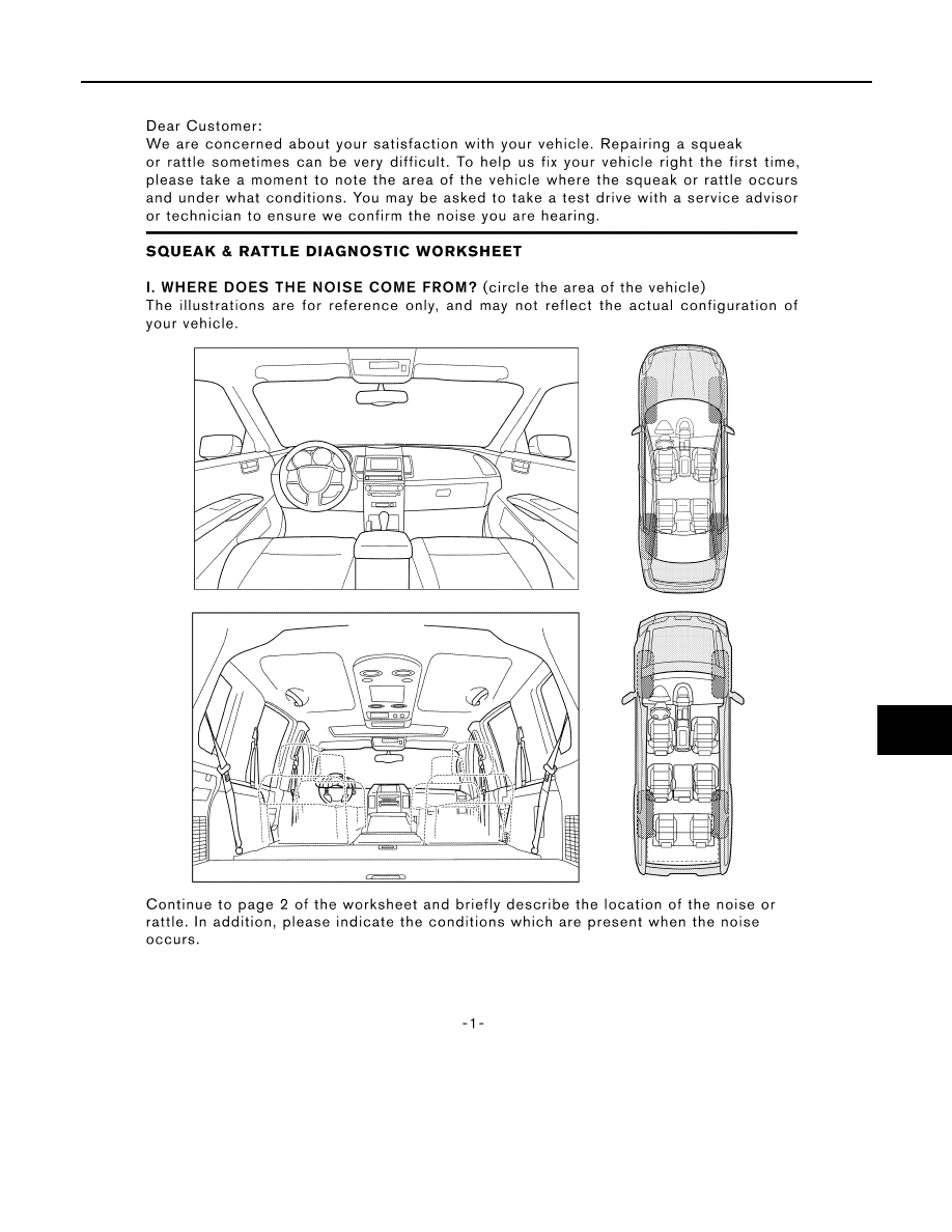
Diagnostic Worksheet

INFOID:0000000007355970

LAIA0072E

August 2012

2012 Pathfinder

RF-44

< SYMPTOM DIAGNOSIS >

SQUEAK AND RATTLE TROUBLE DIAGNOSES

LAIA0071E

August 2012

2012 Pathfinder

PRECAUTIONS

RF-45

< PRECAUTION >

C

D

E

F

G

H

I

J

L

M

A

B

RF

N

O

P

PRECAUTION

PRECAUTIONS

Precaution for Supplemental Restraint System (SRS) "AIR BAG" and "SEAT BELT 
PRE-TENSIONER"

INFOID:0000000007355971

The Supplemental Restraint System such as “AIR BAG” and “SEAT BELT PRE-TENSIONER”, used along

with a front seat belt, helps to reduce the risk or severity of injury to the driver and front passenger for certain

types of collision. This system includes seat belt switch inputs and dual stage front air bag modules. The SRS

system uses the seat belt switches to determine the front air bag deployment, and may only deploy one front

air bag, depending on the severity of a collision and whether the front occupants are belted or unbelted.

Information necessary to service the system safely is included in the SR and SB section of this Service Man-

ual.

WARNING:

• To avoid rendering the SRS inoperative, which could increase the risk of personal injury or death in

the event of a collision which would result in air bag inflation, all maintenance must be performed by

an authorized NISSAN/INFINITI dealer.

• Improper maintenance, including incorrect removal and installation of the SRS, can lead to personal

injury caused by unintentional activation of the system. For removal of Spiral Cable and Air Bag

Module, see the SR section.

• Do not use electrical test equipment on any circuit related to the SRS unless instructed to in this

Service Manual. SRS wiring harnesses can be identified by yellow and/or orange harnesses or har-

ness connectors.

PRECAUTIONS WHEN USING POWER TOOLS (AIR OR ELECTRIC) AND HAMMERS

WARNING:

• When working near the Airbag Diagnosis Sensor Unit or other Airbag System sensors with the Igni-

tion ON or engine running, DO NOT use air or electric power tools or strike near the sensor(s) with a

hammer. Heavy vibration could activate the sensor(s) and deploy the air bag(s), possibly causing

serious injury.

• When using air or electric power tools or hammers, always switch the Ignition OFF, disconnect the

battery, and wait at least 3 minutes before performing any service.

Precaution Necessary for Steering Wheel Rotation After Battery Disconnect

INFOID:0000000007355972

NOTE:

• This Procedure is applied only to models with Intelligent Key system and NATS (NISSAN ANTI-THEFT SYS-

TEM).

• Remove and install all control units after disconnecting both battery cables with the ignition knob in the

LOCK

 position.

• Always use CONSULT to perform self-diagnosis as a part of each function inspection after finishing work. If

DTC is detected, perform trouble diagnosis according to self-diagnostic results.

For models equipped with the Intelligent Key system and NATS, an electrically controlled steering lock mech-

anism is adopted on the key cylinder.

For this reason, if the battery is disconnected or if the battery is discharged, the steering wheel will lock and

steering wheel rotation will become impossible.

If steering wheel rotation is required when battery power is interrupted, follow the procedure below before

starting the repair operation.

OPERATION PROCEDURE

1. Connect both battery cables.

NOTE:

Supply power using jumper cables if battery is discharged.

2. Use the Intelligent Key or mechanical key to turn the ignition switch to the 

ACC

 position. At this time, the

steering lock will be released.

3. Disconnect both battery cables. The steering lock will remain released and the steering wheel can be

rotated.

4. Perform the necessary repair operation.

August 2012

2012 Pathfinder

RF-46

< PRECAUTION >

PRECAUTIONS

5. When the repair work is completed, return the ignition switch to the 

LOCK

 position before connecting

the battery cables. (At this time, the steering lock mechanism will engage.)

6. Perform a self-diagnosis check of all control units using CONSULT. 

Precaution for Work

INFOID:0000000007355973

• When removing or disassembling each component, be careful not to damage or deform it. If a component

may be subject to interference, be sure to protect it with a shop cloth.

• When removing (disengaging) components with a screwdriver or similar tool, be sure to wrap the component

with a shop cloth or vinyl tape to protect it.

• Protect the removed parts with a shop cloth and prevent them from being dropped.

• Replace a deformed or damaged clip.

• If a part is specified as a non-reusable part, always replace it with new one.

• Be sure to tighten bolts and nuts securely to the specified torque.

• After installation is complete, be sure to check that each part works properly.

• Follow the steps below to clean components.

- Water soluble dirt: Dip a soft cloth into lukewarm water, and wring the water out of the cloth to wipe the dirty

area.

Then rub with a soft and dry cloth.

- Oily dirt: Dip a soft cloth into lukewarm water with mild detergent (concentration: within 2 to 3%), and wipe

the dirty area.

Then dip a cloth into fresh water, and wring the water out of the cloth to wipe the detergent off. Then rub with

a soft and dry cloth.

• Do not use organic solvent such as thinner, benzene, alcohol, or gasoline.

• For genuine leather seats, use a genuine leather seat cleaner.

August 2012

2012 Pathfinder

PREPARATION

RF-47

< PREPARATION >

C

D

E

F

G

H

I

J

L

M

A

B

RF

N

O

P

PREPARATION

PREPARATION

Special Service Tool

INFOID:0000000007355974

The actual shapes of Kent-Moore tools may differ from those of special service tools illustrated here.

Commercial Service Tool

INFOID:0000000007355975

Tool number
(Kent-Moore No.)
Tool name

Description

(J-39570)
Chassis ear

Locating the noise

(J-43980)
NISSAN Squeak and
Rattle Kit

Repairing the cause of noise

SIIA0993E

SIIA0994E

(Kent-Moore No.)
Tool name

Description

(J-39565)
Engine ear

Locating the noise

SIIA0995E

August 2012

2012 Pathfinder

RF-48

< REMOVAL AND INSTALLATION >

SUNROOF SYSTEM

REMOVAL AND INSTALLATION

SUNROOF SYSTEM

Adjustment

INFOID:0000000007355976

Inspect then measure the gap and height difference between the glass lid assembly and roof panel; compare

to specifications. Determine which procedure to follow based on results of measurements. 

GAP ADJUSTMENT 

If a gap or minor height difference between glass lid assembly and roof panel is found, adjust in the following

manner:
1. Open sunshade assembly and tilt glass lid assembly up.
2. Loosen glass lid assembly screws (two each on left and right sides), then tilt glass lid assembly down.
3. Manually adjust glass lid assembly from outside of vehicle so it is within specification "A-A" as shown.
4. After adjustment, tilt glass lid assembly up and tighten screws.
5. Tilt glass lid assembly up and down several times to check that it moves and seals properly.

HEIGHT DIFFERENCE ADJUSTMENT

If an excessive height difference between glass lid assembly and roof panel is found, adjust in the following

manner:
1. Remove headlining. Refer to 

INT-22, "Removal and Installation"

.

2. Loosen sunroof unit nuts and sunroof bracket bolts.
3. Add shims until gap is within specification "A-A" as shown.

NOTE:

Temporarily snug nuts and bolts to prevent movement between each adjustment.

4. Tilt glass lid assembly up and down several times to check that it moves and seals properly.
5. Tighten sunroof unit nuts and sunroof bracket bolts. 

NOTE:

A.

0.8 

±

 1.5mm (0.03 

±

 0.06 in.)

B.

5.4 mm (0.21 in)

WIIA1071E

August 2012

2012 Pathfinder

SUNROOF SYSTEM

RF-49

< REMOVAL AND INSTALLATION >

C

D

E

F

G

H

I

J

L

M

A

B

RF

N

O

P

First tighten left front then right rear sunroof unit nuts to prevent uneven torque while tightening remaining

sunroof bracket bolts.

6. Install headlining. Refer to 

INT-22, "Removal and Installation"

.

Removal and Installation

INFOID:0000000007355977

ALKIA1899GB

August 2012

2012 Pathfinder

RF-50

< REMOVAL AND INSTALLATION >

SUNROOF SYSTEM

CAUTION:

• Always work with a helper.

• Handle glass lid assembly with care so not to cause damage.

• Before removal, fully close the glass lid assembly. Then, after removal, do not move the motor

assembly.

• After installing the sunroof and glass lid assembly, check gap adjustment to ensure there is no mal-

function.

NOTE:

• After any adjustment, check sunroof operation and glass lid assembly alignment.

• For easier installation, mark each point before removal.

SUNROOF UNIT

Removal

CAUTION:

• When taking sunroof unit out, use shop cloths to protect the seats and trim from damage.

1. Remove headlining. Refer to 

INT-22, "Removal and Installation"

2. Remove the glass lid assembly. Refer to GLASS LID ASSEMBLY REMOVAL AND INSTALLATION proce-

dure in this section.

3. Disconnect sunroof motor assembly, and remove the front roof console bracket.
4. Disconnect the drain hoses.
5. Remove front sunroof unit nuts.
6. Remove the rear sunroof bracket bolts. 
7. Remove the side nuts, then lower the sunroof unit from the roof panel opening.
8. Remove the sunshade assembly from the rear end of the sunroof unit. Refer to SUNSHADE ASSEMBLY

REMOVAL AND INSTALLATION procedure in this section

Installation

1. Install the sunshade assembly to the rear end of the sunroof unit. Refer to SUNSHADE ASSEMBLY

REMOVAL AND INSTALLATION procedure in this section

2. Position the sunroof unit and install the side nuts.
3. Install the rear sunroof brackets and bolts.
4. Install front sunroof unit nuts.
5. Connect the drain hoses.
6. Install the front roof console bracket, then connect the sunroof motor assembly.
7. Install the glass lid assembly. Refer to GLASS LID ASSEMBLY REMOVAL AND INSTALLATION proce-

dure in this section.

8. Install headlining. Refer to 

INT-22, "Removal and Installation"

.

GLASS LID ASSEMBLY

Removal

1. Open sunshade assembly.
2. Ensure glass lid assembly is closed.
3. Remove the screws securing glass lid assembly to the sunroof unit.
4. Remove the glass lid assembly.

Installation

1. Position glass lid assembly to sunroof unit.

1. Glass lid assembly

2.

Sunroof lid seal

3. Wind deflector

4. Rear drain hoses

5.

Sunshade stoppers

6. Sunroof bracket

7. Sunroof unit

8.

Front drain hoses

9. Sunroof motor assembly

10. Sunshade assembly

August 2012

2012 Pathfinder


Content      ..     512      513      514      515     ..