Nissan Pathfinder (2012 year). Manual - part 344


  Index      Manuals     Nissan Pathfinder (2012 year) - Service and Repair Manual


Search            copyright infringement  


Content      ..     342      343      344      345     ..


Nissan Pathfinder (2012 year). Manual - part 344


P0605 ECM

EC-833

< DTC/CIRCUIT DIAGNOSIS >

[VK56DE]

C

D

E

F

G

H

I

J

K

L

M

A

EC

N

P

O

P0605 ECM

Component Description

INFOID:0000000007358710

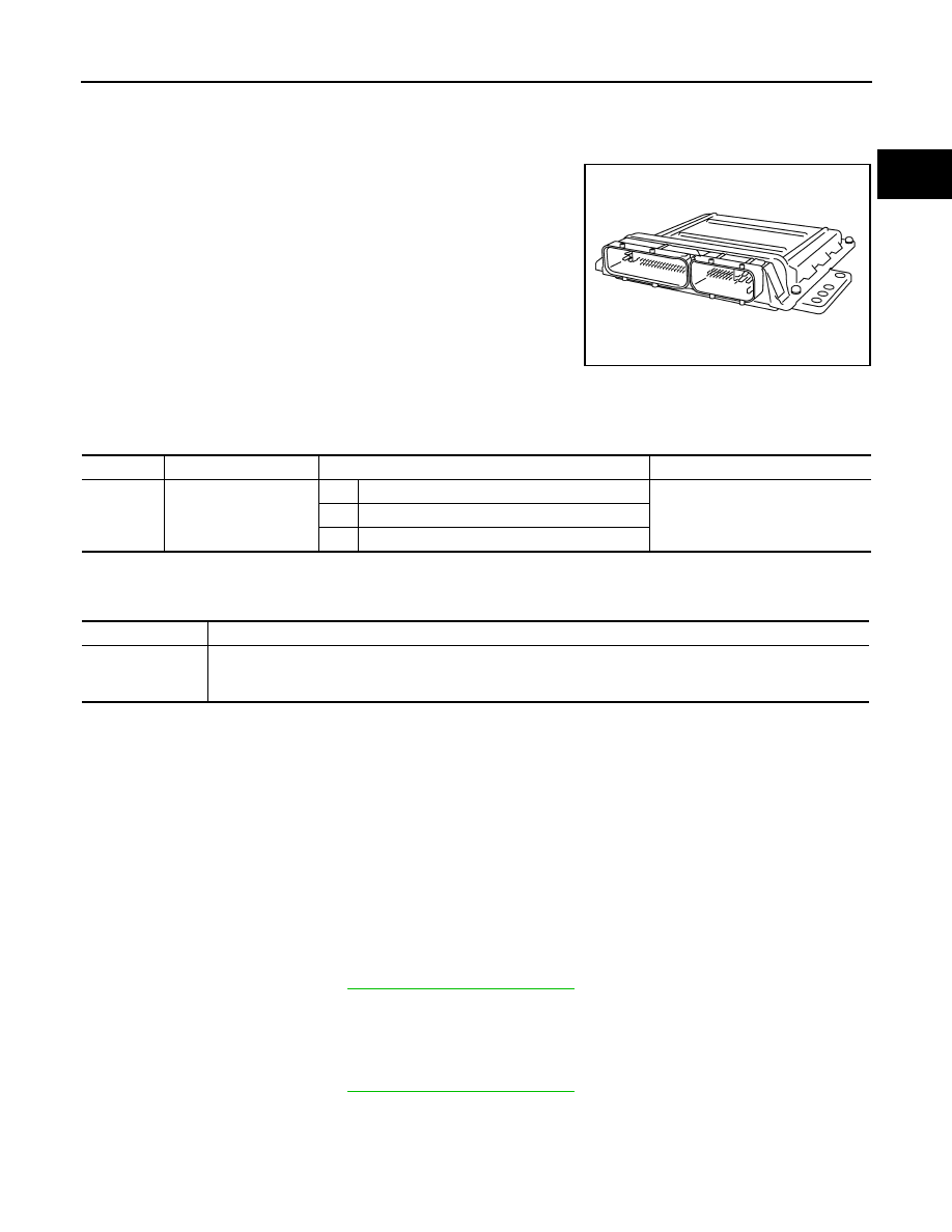
The ECM consists of a microcomputer and connectors for signal

input and output and for power supply. The ECM controls the engine.

On Board Diagnosis Logic

INFOID:0000000007358711

This self-diagnosis has one or two trip detection logic.

FAIL-SAFE MODE

ECM enters fail-safe mode when the malfunction A is detected.

DTC Confirmation Procedure

INFOID:0000000007358712

Perform PROCEDURE FOR MALFUNCTION A first. If the 1st trip DTC cannot be confirmed, perform

PROCEDURE FOR MALFUNCTION B. If there is no malfunction on PROCEDURE FOR MALFUNCTION

B, perform PROCEDURE FOR MALFUNCTION C.

NOTE:

If DTC Confirmation Procedure has been previously conducted, always perform the following procedure

before conducting the next step.

1. Turn ignition switch OFF and wait at least 10 seconds.

2. Turn ignition switch ON.

3. Turn ignition switch OFF and wait at least 10 seconds.

PROCEDURE FOR MALFUNCTION A

1. Turn ignition switch ON.

2. Check 1st trip DTC.

3. If 1st trip DTC is detected, go to 

EC-834, "Diagnosis Procedure"

.

PROCEDURE FOR MALFUNCTION B

1. Turn ignition switch ON and wait at least 1 second.

2. Turn ignition switch OFF, wait at least 10 seconds and then turn it ON.

3. Check 1st trip DTC.

4. If 1st trip DTC is detected, go to 

EC-834, "Diagnosis Procedure"

.

PROCEDURE FOR MALFUNCTION C

1. Turn ignition switch ON and wait at least 1 second.

2. Turn ignition switch OFF, wait at least 10 seconds and then turn it ON.

3. Repeat step 2 for 32 times.

PBIB1164E

DTC No.

Trouble diagnosis name

DTC detecting condition

Possible cause

P0605
0605

Engine control module

A)

ECM calculation function is malfunctioning.

• ECM

B)

ECM EEP-ROM system is malfunctioning.

C)

ECM self shut-off function is malfunctioning.

Detected items

Engine operation condition in fail-safe mode

Malfunction A

• ECM stops the electric throttle control actuator control, throttle valve is maintained at a fixed opening (approx. 

5 degrees) by the return spring.

• ECM deactivates ASCD operation.

August 2012

2012 Pathfinder

EC-834

< DTC/CIRCUIT DIAGNOSIS >

[VK56DE]

P0605 ECM

4. Check 1st trip DTC.

5. If 1st trip DTC is detected, go to 

EC-834, "Diagnosis Procedure"

.

Diagnosis Procedure

INFOID:0000000007358713

1.

INSPECTION START

1. Turn ignition switch ON.

2. Erase DTC.

3. Perform DTC Confirmation Procedure. Refer to 

EC-833, "DTC Confirmation Procedure"

.

4. Is the 1st trip DTC P0605 displayed again?
Yes or No

Yes

>> GO TO 2.

No

>>

INSPECTION END

2.

REPLACE ECM

1. Replace ECM.

2. Perform initialization of NVIS(NATS) system and registration of all NVIS(NATS) ignition key IDs. Refer to

SEC-10, "ECM RE-COMMUNICATING FUNCTION : Special Repair Requirement"

 (with intelligent key

system) or 

SEC-120, "ECM RE-COMMUNICATING FUNCTION : Special Repair Requirement"

 (without

intelligent key system).

3. Perform 

EC-596, "VIN Registration"

.

4. Perform 

EC-597, "Accelerator Pedal Released Position Learning"

.

5. Perform 

EC-597, "Throttle Valve Closed Position Learning"

.

6. Perform 

EC-597, "Idle Air Volume Learning"

.

>>

INSPECTION END

August 2012

2012 Pathfinder

P0607 ECM

EC-835

< DTC/CIRCUIT DIAGNOSIS >

[VK56DE]

C

D

E

F

G

H

I

J

K

L

M

A

EC

N

P

O

P0607 ECM

Description

INFOID:0000000007358714

CAN (Controller Area Network) is a serial communication line for real time application. It is an on-vehicle mul-

tiplex communication line with high data communication speed and excellent error detection ability. Many elec-

tronic control units are equipped onto a vehicle, and each control unit shares information and links with other

control units during operation (not independent). In CAN communication, control units are connected with 2

communication lines (CAN H line, CAN L line) allowing a high rate of information transmission with less wiring.

Each control unit transmits/receives data but selectively reads required data only.

On Board Diagnosis Logic

INFOID:0000000007358715

This self-diagnosis has the one trip detection logic.

DTC Confirmation Procedure

INFOID:0000000007358716

1. Turn ignition switch ON.
2. Check DTC.
3. If DTC is detected, go to 

EC-835, "Diagnosis Procedure"

.

Diagnosis Procedure

INFOID:0000000007358717

1.

INSPECTION START

1. Turn ignition switch ON.

2. Erase DTC.

3. Perform DTC Confirmation Procedure. Refer to 

EC-835, "DTC Confirmation Procedure"

.

4. Is the DTC P0607 displayed again?
Yes or No

Yes

>> GO TO 2.

No

>>

INSPECTION END

2.

REPLACE ECM

1. Replace ECM.

2. Perform initialization of NVIS(NATS) system and registration of all NVIS(NATS) ignition key IDs. Refer to

SEC-10, "ECM RE-COMMUNICATING FUNCTION : Special Repair Requirement"

 (with intelligent key

system) or 

SEC-120, "ECM RE-COMMUNICATING FUNCTION : Special Repair Requirement"

 (without

intelligent key system).

3. Perform 

EC-596, "VIN Registration"

.

4. Perform 

EC-597, "Accelerator Pedal Released Position Learning"

.

5. Perform 

EC-597, "Throttle Valve Closed Position Learning"

.

6. Perform 

EC-597, "Idle Air Volume Learning"

.

>>

INSPECTION END

DTC No.

Trouble diagnosis name

DTC detecting condition

Possible cause

P0607
0607

CAN communication bus

When detecting error during the initial diagnosis 
of CAN controller of ECM.

• ECM

August 2012

2012 Pathfinder

EC-836

< DTC/CIRCUIT DIAGNOSIS >

[VK56DE]

P0643 SENSOR POWER SUPPLY

P0643 SENSOR POWER SUPPLY

On Board Diagnosis Logic

INFOID:0000000007358718

This self-diagnosis has the one trip detection logic.

FAIL-SAFE MODE

When the malfunction is detected, ECM enters fail-safe mode and the MIL illuminates. 

DTC Confirmation Procedure

INFOID:0000000007358719

NOTE:

If DTC Confirmation Procedure has been previously conducted, always perform the following procedure

before conducting the next step.

1. Turn ignition switch OFF and wait at least 10 seconds.

2. Turn ignition switch ON.

3. Turn ignition switch OFF and wait at least 10 seconds.

TESTING CONDITION:

Before performing the following procedure, confirm that battery voltage is more than 10 V at idle.

1. Start engine and let it idle for 1 second.
2. Check DTC.
3. If DTC is detected, go to 

EC-836, "Diagnosis Procedure"

.

Diagnosis Procedure

INFOID:0000000007358720

1.

CHECK GROUND CONNECTIONS

1. Turn ignition switch OFF.

2. Loosen and retighten ground screws on the body.

Refer to 

EC-623, "Ground Inspection"

.

OK or NG

OK

>> GO TO 2.

DTC No.

Trouble diagnosis name

DTC detecting condition

Possible cause

P0643
0643

Sensor power supply 
circuit short

ECM detects that the voltage of power 
source for sensor is excessively low or high.

• Harness or connectors

(APP sensor 1 circuit is shorted.)
(Battery current sensor circuit is shorted.)
(EVAP control system pressure sensor circuit is 
shorted.)
(PSP sensor circuit is shorted.)
(Refrigerant pressure sensor circuit is shorted.)

• Accelerator pedal position sensor
• Battery current sensor
• EVAP control system pressure sensor
• Power steering pressure sensor
• Refrigerant pressure sensor

Engine operation condition in fail-safe mode

ECM stops the electric throttle control actuator control, throttle valve is maintained at a fixed opening (approx. 5 degrees) by the return 
spring.

BBIA0539E

August 2012

2012 Pathfinder

P0643 SENSOR POWER SUPPLY

EC-837

< DTC/CIRCUIT DIAGNOSIS >

[VK56DE]

C

D

E

F

G

H

I

J

K

L

M

A

EC

N

P

O

NG

>> Repair or replace ground connections.

2.

CHECK APP SENSOR 1 POWER SUPPLY CIRCUIT

1. Disconnect accelerator pedal position (APP) sensor (1) harness

connector.

2. Turn ignition switch ON.

3. Check voltage between APP sensor terminal 2 and ground with

CONSULT or tester.

OK or NG

OK

>> GO TO 5.

NG

>> GO TO 3.

3.

CHECK SENSOR POWER SUPPLY CIRCUITS

Check harness for short to power and short to ground, between the following terminals

OK or NG

OK

>> GO TO 4.

NG

>> Repair short to ground or short to power in harness or connectors.

4.

CHECK COMPONENTS

Check the following.

• EVAP control system pressure sensor (Refer to 

EC-788, "Component Inspection"

.)

• Power steering pressure sensor (Refer to 

EC-830, "Component Inspection"

.)

• Battery current sensor (Refer to 

EC-859, "Component Inspection"

.)

• Refrigerant pressure sensor. (Refer to 

EC-944, "Diagnosis Procedure"

.)

OK or NG

OK

>> GO TO 7.

NG

>> Replace malfunctioning components.

5.

CHECK ACCELERATOR PEEDAL POSITION SENSOR

Refer to 

EC-898, "Component Inspection"

.

OK or NG

OK

>> GO TO 7.

NG

>> GO TO 6.

AWBIA0079ZZ

Voltage: Approximately 5 V

PBIB2608E

ECM terminal

Sensor terminal

Reference Wiring Diagram

48

EVAP control system pressure sensor terminal 3

EC-567, "Wiring Diagram"

49

Refrigerant pressure sensor terminal 1

Battery current sensor terminal 1

68

Power steering pressure sensor terminal 1

90

APP sensor terminal 2

August 2012

2012 Pathfinder

EC-838

< DTC/CIRCUIT DIAGNOSIS >

[VK56DE]

P0643 SENSOR POWER SUPPLY

6.

REPLACE ACCELERATOR PEDAL ASSEMBLY

1. Replace accelerator pedal position assembly. Refer to 

ACC-4

.

2. Perform 

EC-597, "Accelerator Pedal Released Position Learning"

.

3. Perform 

EC-597, "Throttle Valve Closed Position Learning"

.

4. Perform 

EC-597, "Idle Air Volume Learning"

.

>>

INSPECTION END

7.

CHECK INTERMITTENT INCIDENT

Refer to 

GI-37, "Intermittent Incident"

.

>>

INSPECTION END

August 2012

2012 Pathfinder

P0850 PNP SWITCH

EC-839

< DTC/CIRCUIT DIAGNOSIS >

[VK56DE]

C

D

E

F

G

H

I

J

K

L

M

A

EC

N

P

O

P0850 PNP SWITCH

Component Description

INFOID:0000000007358721

When the selector lever position is P or N, park/neutral position (PNP) signal is sent to ECM from TCM via

combination meter (unified meter control unit).

ECM detects the position because the continuity of the line (the ON signal) exists.

On Board Diagnosis Logic

INFOID:0000000007358722

DTC Confirmation Procedure

INFOID:0000000007358723

CAUTION:

Always drive vehicle at a safe speed.

NOTE:

If DTC Confirmation Procedure has been previously conducted, always perform the following procedure

before conducting the next step.

1. Turn ignition switch OFF and wait at least 10 seconds.

2. Turn ignition switch ON.

3. Turn ignition switch OFF and wait at least 10 seconds.

 WITH CONSULT

1. Turn ignition switch ON.

2. Select “P/N POSI SW” in “DATA MONITOR” mode with CONSULT. Then check the “P/N POSI SW” indi-

cation under the following conditions.

If NG, go to 

EC-840, "Diagnosis Procedure"

.

If OK, go to following step.

3. Select “DATA MONITOR” mode with CONSULT.

4. Start engine and warm it up to normal operating temperature.

5. Maintain the following conditions for at least 60 consecutive seconds.

6. Check 1st trip DTC.

7. If 1st trip DTC is detected, go to 

EC-840, "Diagnosis Procedure"

.

Overall Function Check

INFOID:0000000007358724

Use this procedure to check the overall function of the park/neutral position (PNP) signal circuit. During this

check, a 1st trip DTC might not be confirmed.

 WITH GST

DTC No.

Trouble diagnosis name

DTC detecting condition

Possible cause

P0850
0850

Park/neutral position 
switch

The park/neutral position (PNP) signal does not 
change during driving after engine is started.

• Harness or connectors

[The park/neutral position (PNP) signal 
circuit is open or shorted.]

• Combination meter (unified meter control 

unit)

• TCM

Selector lever position

Known-good signal

N or P position

ON

Except the above position

OFF

ENG SPEED

1,050 - 6,375 rpm

COOLAN TEMP/S

More than 70

°

C (158

°

F)

B/FUEL SCHDL

3.5 - 31.8 msec

VHCL SPEED SE

More than 64 km/h (40 MPH)

Selector lever

Suitable position

August 2012

2012 Pathfinder

EC-840

< DTC/CIRCUIT DIAGNOSIS >

[VK56DE]

P0850 PNP SWITCH

1. Turn ignition switch ON.

2. Check voltage between ECM terminal 102 (PNP signal) and

ground under the following conditions.

3. If NG, go to 

EC-840, "Diagnosis Procedure"

.

Diagnosis Procedure

INFOID:0000000007358725

1.

CHECK DTC WITH TCM

 Refer to 

TM-35, "OBD-II Diagnostic Trouble Code (DTC)"

.

OK or NG

OK

>> GO TO 2.

NG

>> Repair or replace malfunctioning part.

2.

CHECK STARTING SYSTEM

Turn ignition switch OFF, then turn it to START.

Does starter motor operate?

Yes or No

Yes

>> GO TO 3.

No

>> Refer to 

STR-5, "Work Flow (With GR8-1200 NI)"

 or 

STR-9, "Work Flow (Without GR8-1200 NI)"

.

3.

CHECK PNP SIGNAL CIRCUIT FOR OPEN AND SHORT

1. Turn ignition switch OFF.

2. Disconnect ECM harness connector.

3. Disconnect combination meter harness connector.

4. Check harness continuity between ECM terminal 102 and combination meter terminal 7.

Refer to Wiring Diagram.

5. Also check harness for short to ground and short to power.
OK or NG

OK

>> GO TO 5.

NG

>> GO TO 4.

4.

 DETECT MALFUNCTIONING PART

Check the following.

• Harness connectors M31, E152

• Harness for open or short between ECM and combination meter

>> Repair open circuit or short to ground or short to power in harness or connectors.

5.

CHECK INTERMITTENT INCIDENT

Refer to 

GI-37, "Intermittent Incident"

.

OK or NG

OK

>> GO TO 6.

NG

>> Repair or replace malfunctioning part.

6.

REPLACE COMBINATION METER FUNCTION

Refer to 

MWI-89, "Removal and Installation"

.

Selector lever position

Voltage (Known good data)

P or N position

Approx. 0 V

Except the above position

BATTERY VOLTAGE

(11 - 14 V)

MBIB0043E

Continuity should exist.

August 2012

2012 Pathfinder


Content      ..     342      343      344      345     ..