Nissan Pathfinder (2012 year). Manual - part 331


  Index      Manuals     Nissan Pathfinder (2012 year) - Service and Repair Manual


Search            copyright infringement  


Content      ..     329      330      331      332     ..


Nissan Pathfinder (2012 year). Manual - part 331


P0182, P0183 FTT SENSOR

EC-729

< DTC/CIRCUIT DIAGNOSIS >

[VK56DE]

C

D

E

F

G

H

I

J

K

L

M

A

EC

N

P

O

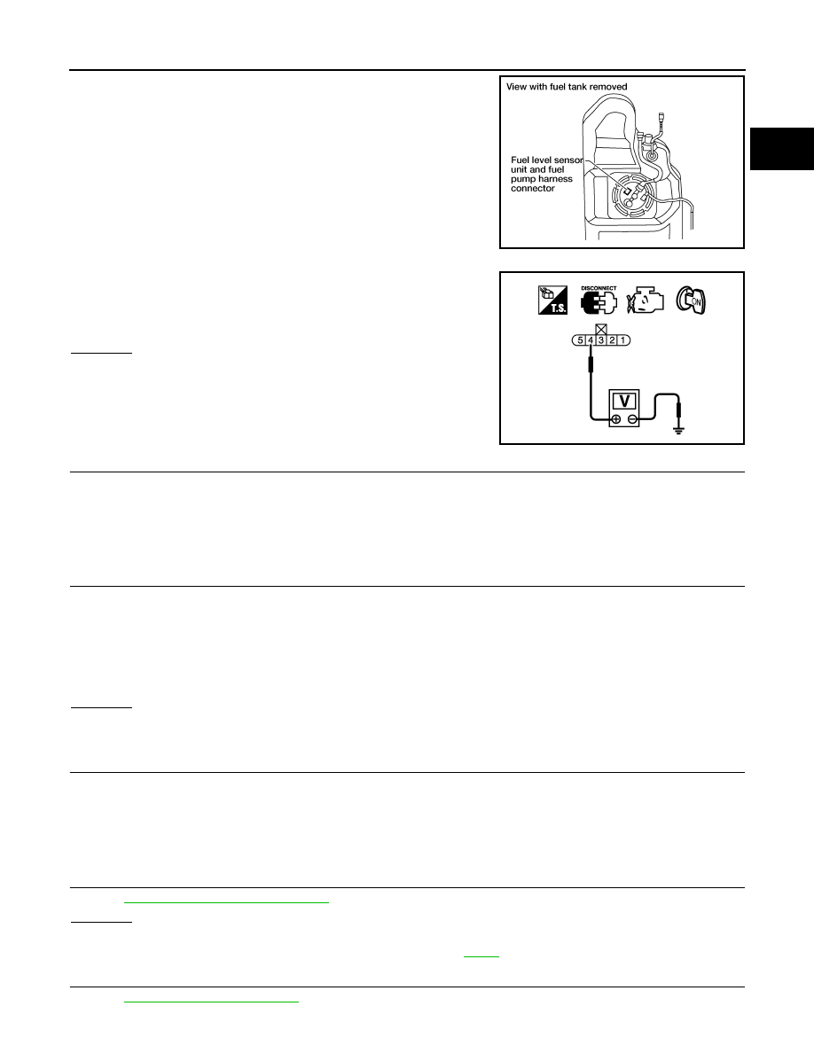
2. Disconnect “fuel level sensor unit and fuel pump” harness con-

nector.

3. Turn ignition switch ON.

4. Check voltage between “fuel level sensor unit and fuel pump”

terminal 4 and ground with CONSULT or tester.

OK or NG

OK

>> GO TO 3.

NG

>> GO TO 2.

2.

DETECT MALFUNCTIONING PART

Check the following.

• Harness connectors C1, E41

• Harness for open or short between ECM and “fuel level sensor unit and fuel pump”

>> Repair harness or connector.

3.

CHECK FUEL TANK TEMPERATURE SENSOR GROUND CIRCUIT FOR OPEN AND SHORT

1. Turn ignition switch OFF.

2. Check harness continuity between “fuel level sensor unit and fuel pump” terminal 3 and ground.

Refer to Wiring Diagram.

3. Also check harness for short to power.
OK or NG

OK

>> GO TO 5.

NG

>> GO TO 4.

4.

DETECT MALFUNCTIONING PART

Check the following.

• Harness connectors C1, E41

• Harness for open or short between “fuel level sensor unit and fuel pump” and ground

>> Repair open circuit or short to power in harness or connector.

5.

CHECK FUEL TANK TEMPERATURE SENSOR

Refer to 

EC-730, "Component Inspection"

.

OK or NG

OK

>> GO TO 6.

NG

>> Replace “fuel level sensor unit fuel pump”. Refer to 

FL-11

.

6.

CHECK INTERMITTENT INCIDENT

Refer to 

GI-37, "Intermittent Incident"

.

BBIA0545E

Voltage: Approximately 5 V

PBIB0932E

Continuity should exist.

August 2012

2012 Pathfinder

EC-730

< DTC/CIRCUIT DIAGNOSIS >

[VK56DE]

P0182, P0183 FTT SENSOR

>>

INSPECTION END

Component Inspection

INFOID:0000000007358596

FUEL TANK TEMPERATURE SENSOR

1. Remove “fuel level sensor unit and fuel pump”. Refer to 

FL-11

.

2. Check resistance between “fuel level sensor unit and fuel pump”

terminals 3 and 4 by heating with hot water as shown in the fig-

ure.

3. If NG, replace “fuel level sensor unit and fuel pump”. Refer to 

FL-

11

.

Temperature [

°

C (

°

F)]

Resistance (k

)

20 (68)

2.3 - 2.7

 50 (122)

0.79 - 0.90

SEF476YA

August 2012

2012 Pathfinder

P0222, P0223 TP SENSOR

EC-731

< DTC/CIRCUIT DIAGNOSIS >

[VK56DE]

C

D

E

F

G

H

I

J

K

L

M

A

EC

N

P

O

P0222, P0223 TP SENSOR

Component Description

INFOID:0000000007358597

Electric throttle control actuator consists of throttle control motor,

throttle position sensor, etc. The throttle position sensor responds to

the throttle valve movement. 

The throttle position sensor has the two sensors. These sensors are

a kind of potentiometer which transform the throttle valve position

into output voltage, and emit the voltage signals to the ECM. The

ECM judges the current opening angle of the throttle valve from

these signals and controls the throttle valve in response to driving

conditions via the throttle control motor.

On Board Diagnosis Logic

INFOID:0000000007358598

These self-diagnoses have the one trip detection logic.

FAIL-SAFE MODE

When the malfunction is detected, ECM enters fail-safe mode and the MIL illuminates.

DTC Confirmation Procedure

INFOID:0000000007358599

NOTE:

If DTC Confirmation Procedure has been previously conducted, always perform the following procedure

before conducting the next step.

1. Turn ignition switch OFF and wait at least 10 seconds.

2. Turn ignition switch ON.

3. Turn ignition switch OFF and wait at least 10 seconds.

TESTING CONDITION:

Before performing the following procedure, confirm that battery voltage is more than 8 V at idle.

1. Start engine and let it idle for 1 second.
2. Check DTC.
3. If DTC is detected, go to 

EC-731, "Diagnosis Procedure"

.

Diagnosis Procedure

INFOID:0000000007358600

1.

CHECK GROUND CONNECTIONS

1. Turn ignition switch OFF.

2. Loosen and retighten ground screws on the body.

PBIB0145E

DTC No.

Trouble diagnosis name

DTC detecting condition

Possible cause

P0222
0222

Throttle position sensor 
1 circuit low input

An excessively low voltage from the TP sensor 
1 is sent to ECM.

• Harness or connectors

(TP sensor 1 circuit is open or shorted.)
(APP sensor 2 circuit is shorted.)

• Electric throttle control actuator

(TP sensor 1)

• Accelerator pedal position sensor

(APP sensor 2)

P0223
0223

Throttle position sensor 
1 circuit high input

An excessively high voltage from the TP sensor 
1 is sent to ECM.

Engine operation condition in fail-safe mode

The ECM controls the electric throttle control actuator in regulating the throttle opening in order for the idle position to be within +10 
degrees.
The ECM regulates the opening speed of the throttle valve to be slower than the normal condition.
So, the acceleration will be poor. 

August 2012

2012 Pathfinder

EC-732

< DTC/CIRCUIT DIAGNOSIS >

[VK56DE]

P0222, P0223 TP SENSOR

Refer to 

EC-623, "Ground Inspection"

.

OK or NG

OK

>> GO TO 2.

NG

>> Repair or replace ground connections.

2.

CHECK THROTTLE POSITION SENSOR 1 POWER SUPPLY CIRCUIT-I

1. Disconnect electric throttle control actuator harness connector.

2. Turn ignition switch ON.

3. Check voltage between electric throttle control actuator terminal

2 and ground with CONSULT or tester.

OK or NG

OK

>> GO TO 7.

NG

>> GO TO 3.

3.

CHECK THROTTLE POSITION SENSOR 1 POWER SUPPLY CIRCUIT-II

1. Turn ignition switch OFF.

2. Disconnect ECM harness connector.

3. Check harness continuity between electric throttle control actuator terminal 2 and ECM terminal 47.

Refer to Wiring Diagram.

OK or NG

OK

>> GO TO 4.

NG

>> Repair open circuit.

4.

CHECK SENSOR POWER SUPPLY CIRCUIT

Check harness for short to power and short to ground, between the following terminals.

BBIA0539E

BBIA0371E

Voltage: Approximately 5 V

PBIB2604E

Continuity should exist.

ECM terminal

Sensor terminal

Reference Wiring Diagram

47 

Electric throttle control actuator terminal 2

EC-567, "Wiring Diagram"

91

APP sensor terminal 1

August 2012

2012 Pathfinder

P0222, P0223 TP SENSOR

EC-733

< DTC/CIRCUIT DIAGNOSIS >

[VK56DE]

C

D

E

F

G

H

I

J

K

L

M

A

EC

N

P

O

OK or NG

OK

>> GO TO 5.

NG

>> Repair short to ground or short to power in harness or connectors.

5.

CHECK ACCELERATOR PEDAL POSITION SENSOR

Refer to 

EC-910, "Component Inspection"

.

OK or NG

OK

>> GO TO 11.

NG

>> GO TO 6.

6.

REPLACE ACCELERATOR PEDAL ASSEMBLY

1. Replace the accelerator pedal assembly. Refer to 

ACC-4, "Removal and Installation"

.

2. Perform 

EC-597, "Accelerator Pedal Released Position Learning"

.

3. Perform 

EC-597, "Throttle Valve Closed Position Learning"

.

4. Perform 

EC-597, "Idle Air Volume Learning"

.

>>

INSPECTION END

7.

CHECK THROTTLE POSITION SENSOR 1 GROUND CIRCUIT FOR OPEN AND SHORT

1. Turn ignition switch OFF.

2. Disconnect ECM harness connector.

3. Check harness continuity between electric throttle control actuator terminal 4 and ECM terminal 66.

 Refer to Wiring Diagram.

4. Also check harness for short to ground and short to power.
OK or NG

OK

>> GO TO 8.

NG

>> Repair open circuit or short to ground or short to power in harness or connectors.

8.

CHECK THROTTLE POSITION SENSOR 1 INPUT SIGNAL CIRCUIT FOR OPEN AND SHORT

1. Check harness continuity between ECM terminal 50 and electric throttle control actuator terminal 1.

Refer to Wiring Diagram.

2. Also check harness for short to ground and short to power.
OK or NG

OK

>> GO TO 9.

NG

>> Repair open circuit or short to ground or short to power in harness or connectors.

9.

CHECK THROTTLE POSITION SENSOR

Refer to 

EC-734, "Component Inspection"

.

OK or NG

OK

>> GO TO 11.

NG

>> GO TO 10.

10.

REPLACE ELECTRIC THROTTLE CONTROL ACTUATOR

1. Replace the electric throttle control actuator. Refer to 

EM-165

.

2. Perform 

EC-597, "Throttle Valve Closed Position Learning"

.

3. Perform 

EC-597, "Idle Air Volume Learning"

.

>>

INSPECTION END

11.

CHECK INTERMITTENT INCIDENT

Refer to 

GI-37, "Intermittent Incident"

.

Continuity should exist.

Continuity should exist.

August 2012

2012 Pathfinder

EC-734

< DTC/CIRCUIT DIAGNOSIS >

[VK56DE]

P0222, P0223 TP SENSOR

>>

INSPECTION END

Component Inspection

INFOID:0000000007358601

THROTTLE POSITION SENSOR

1. Reconnect all harness connectors disconnected.
2. Perform 

EC-597, "Throttle Valve Closed Position Learning"

.

3. Turn ignition switch ON.
4. Shift selector lever to the D position. 
5. Check voltage between ECM terminals 50 (TP sensor 1 signal)

and ground, 69 (TP sensor 2 signal) and ground under the fol-

lowing conditions.

6. If NG, replace electric throttle control actuator and go to the next

step. Refer to 

EM-165

.

7. Perform 

EC-597, "Throttle Valve Closed Position Learning"

.

8. Perform 

EC-597, "Idle Air Volume Learning"

.

Terminal

Accelerator pedal

Voltage

50
(Throttle position sensor 1)

Fully released

More than 0.36V

Fully depressed

Less than 4.75V

69
 (Throttle position sensor 2)

Fully released

Less than 4.75V

Fully depressed

More than 0.36V

PBIB1530E

August 2012

2012 Pathfinder

P0300, P0301, P0302, P0303, P0304, P0305, P0306, P0307, P0308 MISFIRE

EC-735

< DTC/CIRCUIT DIAGNOSIS >

[VK56DE]

C

D

E

F

G

H

I

J

K

L

M

A

EC

N

P

O

P0300, P0301, P0302, P0303, P0304, P0305, P0306, P0307, P0308 MIS-
FIRE

On Board Diagnosis Logic

INFOID:0000000007358602

When a misfire occurs, engine speed will fluctuate. If the engine speed fluctuates enough to cause the crank-

shaft position (CKP) sensor (POS) signal to vary, ECM can determine that a misfire is occurring.

The misfire detection logic consists of the following two conditions.
1. One Trip Detection Logic (Three Way Catalyst Damage) 

On the 1st trip, when a misfire condition occurs that can damage the three way catalyst (TWC) due to

overheating, the MIL will blink.

When a misfire condition occurs, the ECM monitors the CKP sensor signal every 200 engine revolutions

for a change.

When the misfire condition decreases to a level that will not damage the TWC, the MIL will turn off.

If another misfire condition occurs that can damage the TWC on a second trip, the MIL will blink.

When the misfire condition decreases to a level that will not damage the TWC, the MIL will remain on.

If another misfire condition occurs that can damage the TWC, the MIL will begin to blink again.

2. Two Trip Detection Logic (Exhaust quality deterioration)

For misfire conditions that will not damage the TWC (but will affect vehicle emissions), the MIL will only

illuminate when the misfire is detected on a second trip. During this condition, the ECM monitors the CKP

sensor signal every 1,000 engine revolutions.

A misfire malfunction can be detected in any one cylinder or in multiple cylinders.

DTC Confirmation Procedure

INFOID:0000000007358603

CAUTION:

Always drive vehicle in safe manner according to traffic conditions and obey all traffic laws when driv-

ing.

1. If DTC Confirmation Procedure has been previously conducted, always perform the following procedure

before conducting the next step.

a. Turn ignition switch OFF and wait at least 10 seconds.
b. Turn ignition switch ON.

Sensor

Input signal to ECM

ECM function

Crankshaft position sensor (POS)

Engine speed

On board diagnosis of misfire

DTC No.

Trouble diagnosis name

DTC detecting condition

Possible cause

P0300
0300

Multiple cylinder misfires detected

Multiple cylinder misfire.

• Improper spark plug
• Insufficient compression
• Incorrect fuel pressure
• The fuel injector circuit is open or shorted
• Fuel injector
• Intake air leakage
• The ignition signal circuit is open or shorted
• Lack of fuel
• Signal plate
• Air fuel ratio (A/F) sensor 1
• Incorrect PCV hose connection

P0301
0301

No.1 cylinder misfire detected

No. 1 cylinder misfires.

P0302
0302

No. 2 cylinder misfire detected

No. 2 cylinder misfires.

P0303
0303

No. 3 cylinder misfire detected

No. 3 cylinder misfires.

P0304
0304

No. 4 cylinder misfire detected

No. 4 cylinder misfires.

P0305
0305

No. 5 cylinder misfire detected

No. 5 cylinder misfires.

P0306
0306

No. 6 cylinder misfire detected

No. 6 cylinder misfires.

P0307
0307

No. 7 cylinder misfire detected

No. 7 cylinder misfires.

P0308
0308

No. 8 cylinder misfire detected

No. 8 cylinder misfires.

August 2012

2012 Pathfinder

EC-736

< DTC/CIRCUIT DIAGNOSIS >

[VK56DE]

P0300, P0301, P0302, P0303, P0304, P0305, P0306, P0307, P0308 MISFIRE

c.

Turn ignition switch OFF and wait at least 10 seconds.

2. Start engine and warm it up to normal operating temperature.
3. Turn ignition switch OFF and wait at least 10 seconds.
4. Turn ignition switch ON.
5. Turn ignition switch OFF and wait at least 10 seconds.
6. Restart engine and let it idle for approximately 15 minutes.
7. Check 1st trip DTC.
8. If 1st trip DTC is detected, go to 

EC-736, "Diagnosis Procedure"

.

NOTE:

If 1st trip DTC is not detected during above procedure, performing the following procedure is advised.

a. Turn ignition switch OFF and wait at least 10 seconds.
b. Turn ignition switch ON.
c.

Turn ignition switch OFF and wait at least 10 seconds.

d. Start engine and drive the vehicle under similar conditions to (1st trip) Freeze Frame Data for a certain

time. Refer to the table below.

Hold the accelerator pedal as steady as possible.

Similar conditions to (1st trip) Freeze Frame Data mean that the following conditions should be satisfied at

the same time.

Driving time varies according to the engine speed in the freeze frame data.

Diagnosis Procedure

INFOID:0000000007358604

1.

CHECK FOR INTAKE AIR LEAKAGE AND PCV HOSE

1. Start engine and run it at idle speed.

2. Listen for the sound of the intake air leakage.

3. Check PCV hose connection.
OK or NG

OK

>> GO TO 2.

NG

>> Discover air leakage location and repair.

2.

CHECK FOR EXHAUST SYSTEM CLOGGING

Stop engine and visually check exhaust tube, three way catalyst and muffler for dents.
OK or NG

OK

>> GO TO 3.

NG

>> Repair or replace malfunctioning part.

3.

PERFORM POWER BALANCE TEST


With CONSULT

1. Perform “POWER BALANCE” in “ACTIVE TEST” mode.

Engine speed

Engine speed in the freeze frame data 

±

 400 rpm

Vehicle speed

Vehicle speed in the freeze frame data 

±

 10 km/h (6 MPH)

Engine coolant temperature (T) 
condition

When the freeze frame data shows lower than 70

°

C (158

°

F),

T should be lower than 70

°

C (158

°

F).

When the freeze frame data shows higher than or equal to 70

°

C (158

°

F),

T should be higher than or equal to 70

°

C (158

°

F).

Engine speed

Time

Around 1,000 rpm

Approximately 10 minutes

Around 2,000 rpm

Approximately 5 minutes

More than 3,000 rpm

Approximately 3.5 minutes

August 2012

2012 Pathfinder


Content      ..     329      330      331      332     ..