Nissan Pathfinder (2012 year). Manual - part 330


  Index      Manuals     Nissan Pathfinder (2012 year) - Service and Repair Manual


Search            copyright infringement  


Content      ..     328      329      330      331     ..


Nissan Pathfinder (2012 year). Manual - part 330


P0172, P0175 FUEL INJECTION SYSTEM FUNCTION

EC-721

< DTC/CIRCUIT DIAGNOSIS >

[VK56DE]

C

D

E

F

G

H

I

J

K

L

M

A

EC

N

P

O

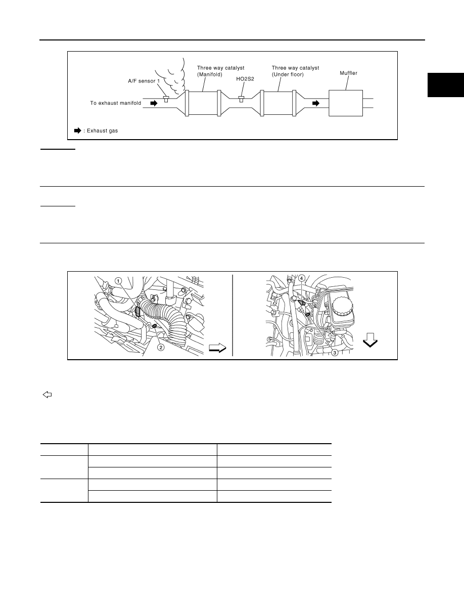
2. Listen for an exhaust gas leakage before three way catalyst (manifold).

OK or NG

OK

>> GO TO 2.

NG

>> Repair or replace malfunctioning part.

2.

CHECK FOR INTAKE AIR LEAKAGE

Listen for an intake air leakage after the mass air flow sensor.
OK or NG

OK

>> GO TO 3.

NG

>> Repair or replace malfunctioning part.

3.

CHECK AIR FUEL RATIO SENSOR 1 INPUT SIGNAL CIRCUIT

1. Turn ignition switch OFF.

2. Disconnect corresponding air fuel ratio (A/F) sensor 1 harness connector.

3. Disconnect ECM harness connector.

4. Check harness continuity between A/F sensor 1 terminals and ECM terminals as per the following.

Refer to Wiring Diagram.

5. Check harness continuity between the following terminals and ground.

Refer to Wiring Diagram.

PBIB1216E

ALBIA0360ZZ

1.

A/F sensor 1 (bank 2) harness connector

2.

A/F sensor 1 (bank 2)

3.

A/F sensor 1 (bank 1)

4.

A/F sensor 1 (bank 1) harness connector
: Vehicle front

A/F sensor 1 terminal

ECM terminal

Bank 1

1

35

2

56

Bank 2

1

16

2

75

Continuity should exist.

August 2012

2012 Pathfinder

EC-722

< DTC/CIRCUIT DIAGNOSIS >

[VK56DE]

P0172, P0175 FUEL INJECTION SYSTEM FUNCTION

6. Also check harness for short to power.
OK or NG

OK

>> GO TO 4.

NG

>> Repair open circuit or short to ground or short to power in harness or connectors.

4.

CHECK FUEL PRESSURE

1. Release fuel pressure to zero. Refer to 

EC-952, "Fuel Pressure Check"

.

2. Install fuel pressure gauge and check fuel pressure. Refer to 

EC-952, "Fuel Pressure Check"

.

OK or NG

OK

>> GO TO 6.

NG

>> GO TO 5.

5.

DETECT MALFUNCTIONING PART

Check the following.

• Fuel pump and circuit (Refer to 

EC-928, "Diagnosis Procedure"

.)

• Fuel pressure regulator (Refer to 

EC-952, "Fuel Pressure Check"

.)

>> Repair or replace malfunctioning part.

6.

CHECK MASS AIR FLOW SENSOR


With CONSULT

1. Install all removed parts.

2. Check “MASS AIR FLOW” in “DATA MONITOR” mode with CONSULT.


With GST

1. Install all removed parts.

2. Check mass air flow sensor signal in Service $01 with GST.

OK or NG

OK

>> GO TO 7.

NG

>> Check connectors for rusted terminals or loose connections in the mass air flow sensor circuit or

grounds. Refer to 

EC-648, "Diagnosis Procedure"

.

7.

CHECK FUNCTION OF FUEL INJECTOR


With CONSULT

1. Start engine.

2. Perform “POWER BALANCE” in “ACTIVE TEST” mode with CONSULT.

3. Check that each circuit produces a momentary engine speed drop.


Without CONSULT

1. Start engine.

Bank 1

Bank 2

A/F sensor 1 terminal

ECM terminal

A/F sensor 1 terminal

ECM terminal

1

35

1

16

2

56

2

75

Continuity should not exist.

At idling: Approximately 350 kPa (3.57 kg/cm

2

, 51 psi)

3.0 - 9.0 g·m/sec:

At idling

9.0 - 28.0 g·m/sec:

At 2,500 rpm

3.0 - 9.0 g·m/sec:

At idling

9.0 - 28.0 g·m/sec:

At 2,500 rpm

August 2012

2012 Pathfinder

P0172, P0175 FUEL INJECTION SYSTEM FUNCTION

EC-723

< DTC/CIRCUIT DIAGNOSIS >

[VK56DE]

C

D

E

F

G

H

I

J

K

L

M

A

EC

N

P

O

2. Listen to each fuel injector operating sound.

OK or NG

OK

>> GO TO 8.

NG

>> Perform trouble diagnosis for FUEL INJECTOR, refer to

EC-925, "Diagnosis Procedure"

.

8.

CHECK FUEL INJECTOR

1. Remove fuel injector assembly. Refer to 

EM-180, "Removal and Installation"

.

Keep fuel hose and all fuel injectors connected to fuel injector gallery.

2. Confirm that the engine is cooled down and there are no fire hazards near the vehicle.

3. Disconnect all fuel injector harness connectors.

4. Disconnect all ignition coil harness connectors.

5. Prepare pans or saucers under each fuel injector.

6. Crank engine for approximately 3 seconds.

Check that fuel does not drip from fuel injector.

OK or NG

OK (Does not drip.)>>GO TO 9.

NG (Drips.)>>Replace the fuel injectors from which fuel is dripping. Refer to 

EM-180

. Always replace O-ring

with new one. 

9.

CHECK INTERMITTENT INCIDENT

Refer to 

GI-37, "Intermittent Incident"

.

>>

INSPECTION END

Clicking noise should be heard.

PBIB1986E

August 2012

2012 Pathfinder

EC-724

< DTC/CIRCUIT DIAGNOSIS >

[VK56DE]

P0181 FTT SENSOR

P0181 FTT SENSOR

Component Description

INFOID:0000000007358587

The fuel tank temperature sensor is used to detect the fuel tempera-

ture inside the fuel tank. The sensor modifies a voltage signal from

the ECM. The modified signal returns to the ECM as the fuel temper-

ature input. The sensor uses a thermistor which is sensitive to the

change in temperature. The electrical resistance of the thermistor

decreases as temperature increases.

<Reference data>

*: These data are reference values and are measured between ECM terminal 107
(Fuel tank temperature sensor) and ground.

CAUTION:

Never use ECM ground terminals when measuring input/output

voltage. Doing so may result in damage to the ECM's transistor.

Use a ground other than ECM terminals, such as the ground.

DTC Logic

INFOID:0000000007358588

DTC DETECTION LOGIC

DTC CONFIRMATION PROCEDURE

1.

PRECONDITIONING

If DTC CONFIRMATION PROCEDURE has been previously conducted, always perform the following proce-

dure before conducting the next test.

1. Turn ignition switch OFF and wait at least 10 seconds.

2. Turn ignition switch ON.

3. Turn ignition switch OFF and wait at least 10 seconds.

>> GO TO 2.

BBIA0545E

Fluid temperature

[

°

C (

°

F)]

Voltage*

(V)

Resistance

(k

)

20 (68)

3.5

2.3 - 2.7

50 (122)

2.2

0.79 - 0.90

SEF012P

DTC No.

Trouble diagnosis

(Trouble diagnosis content)

DTC detecting condition

Possible cause

P0181

FTT SENSOR
[Fuel tank temperature (FTT) 
sensor circuit range/perfor-
mance]

A)

Rationally incorrect voltage from the 
sensor is sent to ECM, compared with 
the voltage signals from ECT sensor 
and intake air temperature sensor.

• Harness or connectors

(The FTT sensor circuit is open or 
shorted)

• FTT sensor

B)

The comparison result of signals trans-
mitted to ECM from each temperature 
sensor (IAT sensor, ECT sensor, and 
FTT sensor) shows that the voltage 
signal of the FTT sensor is higher/low-
er than that of other temperature sen-
sors when the engine is started with its 
cold state.

• Harness or connectors

(High or low resistance in the FTT 
sensor circuit)

• FTT sensor

August 2012

2012 Pathfinder

P0181 FTT SENSOR

EC-725

< DTC/CIRCUIT DIAGNOSIS >

[VK56DE]

C

D

E

F

G

H

I

J

K

L

M

A

EC

N

P

O

2.

PERFORM DTC CONFIRMATION PROCEDURE FOR MALFUNCTION A-I

1. Turn ignition switch ON and wait at least 10 seconds.

2. Check 1st trip DTC.
Is 1st trip DTC detected?

YES

>> Proceed to 

EC-726, "Diagnosis Procedure"

.

NO

>> GO TO 3.

3.

CHECK ENGINE COOLANT TEMPERATURE

With CONSULT

1. Select “COOLAN TEMP/S” in “DATA MONITOR” with CONSULT.

2. Check “COOLAN TEMP/S” value.

With GST

Follow the procedure “With CONSULT” above.
“COOLAN TEMP/S” less than 60

°

C (140

°

F)?

YES

>> INSPECTION END

NO

>> GO TO 4.

4.

PERFORM DTC CONFIRMATION PROCEDURE FOR MALFUNCTION A-II

With CONSULT

1. Cool engine down until “COOLAN TEMP/S” is less than 60

°

C (140

°

F).

2. Wait at least 10 seconds.

3. Check 1st trip DTC.

With GST

Follow the procedure “With CONSULT” above.
Is 1st trip DTC detected?

YES

>> Proceed to 

EC-726, "Diagnosis Procedure"

.

NO

>> GO TO 5.

5.

PERFORM COMPONENT FUNCTION CHECK (FOR MALFUNCTION B)

Perform component function check. Refer to 

EC-725, "Component Function Check"

.

NOTE:

Use the component function check to check the overall function of the FTT sensor circut. During this check, a

1st trip DTC might not be confirmed.
Is the inspection result normal?

YES

>> INSPECTION END

NO

>> Proceed to 

EC-726, "Diagnosis Procedure"

.

Component Function Check

INFOID:0000000007358589

1.

CHECK FUEL TANK TEMPERATURE (FTT) SENSOR

1. Turn ignition switch OFF.

2. Disconnect fuel level sensor unit and fuel pump harness connector.

3. Remove fuel level sensor unit. Refer to 

FL-11

.

4. Check resistance between fuel level sensor unit and fuel pump

terminals by heating with hot water as shown in the figure.

Is the inspection result normal?

YES

>> GO TO 2.

NO

>> Proceed to 

EC-726, "Diagnosis Procedure"

.

2.

CHECK INTERMITTENT INCIDENT

Check intermittent incident. Refer to 

GI-37, "Intermittent Incident"

.

Terminals

Condition

Resistance (k

)

4 and 3

Temperature [

°

C (

°

F)]

20 (68)

2.3 – 2.7

50 (122)

0.79 – 0.90

JMBIA0167ZZ

August 2012

2012 Pathfinder

EC-726

< DTC/CIRCUIT DIAGNOSIS >

[VK56DE]

P0181 FTT SENSOR

Is the inspection result normal?

YES

>> INSPECTION END

NO

>> Proceed to 

EC-726, "Diagnosis Procedure"

.

Diagnosis Procedure

INFOID:0000000007358590

1.

INSPECTION START

Confirm the detected malfunction (A or B). Refer to 

EC-724, "DTC Logic"

.

Which malfunction is detected?

A

>> GO  TO  2.

B

>> GO  TO  6.

2.

CHECK FUEL TANK TEMPERATURE (FTT) SENSOR POWER SUPPLY CIRCUIT

1. Turn ignition switch OFF.

2. Disconnect fuel level sensor unit and fuel pump harness connector.

3. Turn ignition switch ON.

4. Check the voltage between fuel level sensor unit and fuel pump harness connector and ground.

Is the inspection result normal?

YES

>> GO TO 4.

NO

>> GO TO 3.

3.

DETECT MALFUNCTIONING PART

Check the following.

• Harness for open or short between ECM and fuel level sensor unit and fuel pump

• Loose or poor connection for each connector and harness

>> Repair open circuit, short to ground or short to power in harness or connector.

4.

CHECK FTT SENSOR GROUND CIRCUIT FOR OPEN AND SHORT

1. Turn ignition switch OFF.

2. Check the continuity between fuel level sensor unit and fuel pump harness connector and ground.

3. Also check harness for short to ground and short to power.
Is the inspection result normal?

YES

>> GO TO 6.

NO

>> GO TO 5.

5.

DETECT MALFUNCTIONING PART

Check the following.

• Harness for open or short between fuel level sensor unit and fuel pump and ground

• Loose or poor connection for each connector and harness

>> Repair open circuit, short to ground or short to power in harness or connector.

6.

CHECK FTT SENSOR

Check FTT sensor. Refer to 

EC-727, "Component Inspection"

.

Is the inspection result normal?

Fuel level sensor unit and fuel pump

Ground

Voltage (V)

Connector

Terminal

C5

4

Ground

Approx. 5

Fuel level sensor unit and fuel 

pump

Ground

Continuity

Connector

Terminal

C5

3

Ground

Existed

August 2012

2012 Pathfinder

P0181 FTT SENSOR

EC-727

< DTC/CIRCUIT DIAGNOSIS >

[VK56DE]

C

D

E

F

G

H

I

J

K

L

M

A

EC

N

P

O

YES

>> GO TO 7.

NO

>> Replace fuel level sensor unit and fuel pump. Refer to 

FL-11

.

7.

CHECK INTERMITTENT INCIDENT

Check intermittent incident. Refer to 

GI-37, "Intermittent Incident"

.

>> INSPECTION END

Component Inspection

INFOID:0000000007358591

1.

CHECK FUEL TANK TEMPERATURE (FTT) SENSOR

1. Turn ignition switch OFF.

2. Disconnect fuel level sensor unit and fuel pump harness connector.

3. Remove fuel level sensor unit. Refer to 

FL-11

.

4. Check resistance between fuel level sensor unit and fuel pump

terminals by heating with hot water as shown in the figure.

Is the inspection result normal?

YES

>> INSPECTION END

NO

>> Replace fuel level sensor unit and fuel pump. Refer to

FL-11

.

Terminals

Condition

Resistance (k

)

4 and 3

Temperature [

°

C (

°

F)]

20 (68)

2.3 – 2.7

50 (122)

0.79 – 0.90

JMBIA0167ZZ

August 2012

2012 Pathfinder

EC-728

< DTC/CIRCUIT DIAGNOSIS >

[VK56DE]

P0182, P0183 FTT SENSOR

P0182, P0183 FTT SENSOR

Component Description

INFOID:0000000007358592

The fuel tank temperature sensor is used to detect the fuel tempera-

ture inside the fuel tank. The sensor modifies a voltage signal from

the ECM. The modified signal returns to the ECM as the fuel temper-

ature input. The sensor uses a thermistor which is sensitive to the

change in temperature. The electrical resistance of the thermistor

decreases as temperature increases.

<Reference data>

*: These data are reference values and are measured between ECM terminal 107
(Fuel tank temperature sensor) and ground.

CAUTION:

Never use ECM ground terminals when measuring input/output

voltage. Doing so may result in damage to the ECM's transistor.

Use a ground other than ECM terminals, such as the ground.

On Board Diagnosis Logic

INFOID:0000000007358593

DTC Confirmation Procedure

INFOID:0000000007358594

1. If DTC Confirmation Procedure has been previously conducted, always perform the following procedure

before conducting the next step.

a. Turn ignition switch OFF and wait at least 10 seconds.
b. Turn ignition switch ON.
c.

Turn ignition switch OFF and wait at least 10 seconds.

2. Turn ignition switch ON.
3. Wait at least 5 seconds.
4. Check 1st trip DTC.
5. If 1st trip DTC is detected, go to 

EC-728, "Diagnosis Procedure"

.

Diagnosis Procedure

INFOID:0000000007358595

1.

CHECK FUEL TANK TEMPERATURE SENSOR POWER SUPPLY CIRCUIT

1. Turn ignition switch OFF.

BBIA0545E

Fluid temperature

[

°

C (

°

F)]

Voltage*

(V)

Resistance

(k

)

20 (68)

3.5

2.3 - 2.7

50 (122)

2.2

0.79 - 0.90

SEF012P

DTC No.

Trouble diagnosis name

DTC detecting condition

Possible cause

P0182
0182

Fuel tank temperature 
sensor circuit low input

An excessively low voltage from the sensor is 
sent to ECM.

• Harness or connectors

(The sensor circuit is open or shorted.)

• Fuel tank temperature sensor

P0183
0183

Fuel tank temperature 
sensor circuit high input

An excessively high voltage from the sensor is 
sent to ECM.

August 2012

2012 Pathfinder


Content      ..     328      329      330      331     ..