Nissan Pathfinder (2012 year). Manual - part 324


  Index      Manuals     Nissan Pathfinder (2012 year) - Service and Repair Manual


Search            copyright infringement  


Content      ..     322      323      324      325     ..


Nissan Pathfinder (2012 year). Manual - part 324


P0127 IAT SENSOR

EC-673

< DTC/CIRCUIT DIAGNOSIS >

[VK56DE]

C

D

E

F

G

H

I

J

K

L

M

A

EC

N

P

O

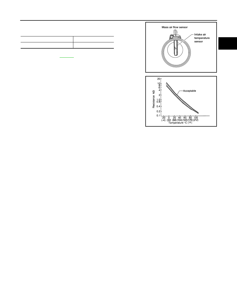
1. Check resistance between intake air temperature sensor termi-

nals 5 and 6 under the following conditions.

2. If NG, replace mass air flow sensor (with intake air temperature

sensor). Refer to 

EM-164

.

Intake air temperature [

°

C (

°

F)]

Resistance (k

)

25 (77)

1.800 - 2.200

BBIA0355E

SEF012P

August 2012

2012 Pathfinder

EC-674

< DTC/CIRCUIT DIAGNOSIS >

[VK56DE]

P0128 THERMOSTAT FUNCTION

P0128 THERMOSTAT FUNCTION

On Board Diagnosis Logic

INFOID:0000000007358542

NOTE:

If DTC P0128 is displayed with DTC P0300, P0301, P0302, P0303, P0304, P0305, P0306, P0307 or P0308,

first perform the trouble diagnosis for DTC P0300, P0301, P0302, P0303, P0304, P0305, P0306, P0307,

P0308. Refer to 

EC-735, "DTC Confirmation Procedure"

.

Engine coolant temperature has not risen enough to open the thermostat even though the engine has run long

enough.

This is due to a leakage in the seal or the thermostat being stuck open.

DTC Confirmation Procedure

INFOID:0000000007358543

NOTE:

If DTC Confirmation Procedure has been previously conducted, always perform the following procedure

before conducting the next step.

1. Turn ignition switch OFF and wait at least 10 seconds.

2. Turn ignition switch ON.

3. Turn ignition switch OFF and wait at least 10 seconds.

 WITH CONSULT

TESTING CONDITION:

For best results, perform at ambient temperature of –10

°

C (14

°

F) or higher.

For best results, perform at engine coolant temperature of –10

°

C (14

°

F) to 56

°

C (133

°

F).

Before performing the following procedure, do not add fuel.

1. Turn A/C switch OFF.
2. Turn blower fan switch OFF.
3. Turn ignition switch ON.
4. Select “COOLAN TEMP/S” in “DATA MONITOR” mode with CONSULT.
5. Check the indication of “COOLAN TEMP/S”.

If it is below 56

°

C (133

°

F), go to next step.

If it is above 56

°

C (133

°

F), cool down the engine to less than 56

°

C (133

°

F). Then go to next steps.

6. Start engine and drive vehicle for 10 consecutive minutes under the following conditions.

If “COOLAN TEMP/S” increases to more than 75

°

C (167

°

F) within 10 minutes, turn ignition switch

OFF because the test result will be OK.

7. Check 1st trip DTC.
8. If 1st trip DTC is detected, go to 

EC-674, "Diagnosis Procedure"

.

 WITH GST

Follow the procedure “WITH CONSULT” above.

Diagnosis Procedure

INFOID:0000000007358544

1.

CHECK ENGINE COOLANT TEMPERATURE SENSOR

Refer to 

EC-675, "Component Inspection"

.

OK or NG

OK

>> GO TO 2.

NG

>> Replace engine coolant temperature sensor. Refer to 

EM-214

.

DTC No.

Trouble diagnosis name

DTC detecting condition

Possible cause

P0128
0128

Thermostat function

The engine coolant temperature does not 
reach to specified temperature even though 
the engine has run long enough.

• Thermostat
• Leakage from sealing portion of thermostat
• Engine coolant temperature sensor

VHCL SPEED SE

More than 56 km/h (35 MP)

August 2012

2012 Pathfinder

P0128 THERMOSTAT FUNCTION

EC-675

< DTC/CIRCUIT DIAGNOSIS >

[VK56DE]

C

D

E

F

G

H

I

J

K

L

M

A

EC

N

P

O

2.

CHECK THERMOSTAT

Refer to 

CO-54, "Removal and Installation"

.

OK or NG

OK

>>

INSPECTION END

NG

>> Replace thermostat. Refer to 

CO-54

.

Component Inspection

INFOID:0000000007358545

ENGINE COOLANT TEMPERATURE SENSOR

1. Check resistance between engine coolant temperature sensor

terminals 1 and 2 as shown in the figure.

2. If NG, replace engine coolant temperature sensor. Refer to 

EM-

214

.

PBIB2005E

Engine coolant temperature [

°

C (

°

F)]

Resistance (k

)

20 (68)

2.1 - 2.9

50 (122)

0.68 - 1.00

90 (194)

 0.236 - 0.260

SEF012P

August 2012

2012 Pathfinder

EC-676

< DTC/CIRCUIT DIAGNOSIS >

[VK56DE]

P0130, P0150 A/F SENSOR 1

P0130, P0150 A/F SENSOR 1

Component Description

INFOID:0000000007358546

The air fuel ratio (A/F) sensor 1 is a planar one-cell limit current sen-

sor. The sensor element of the A/F sensor 1 is composed an elec-

trode layer, which transports ions. It has a heater in the element.
The sensor is capable of precise measurement   = 1, but also in the

lean and rich range. Together with its control electronics, the sensor
outputs a clear, continuous signal throughout a wide   range.

The exhaust gas components diffuse through the diffusion layer at

the sensor cell. An electrode layer is applied voltage, and this current

relative oxygen density in lean. Also this current relative hydrocar-

bon density in rich.

Therefore, the A/F sensor 1 is able to indicate air fuel ratio by this

electrode layer of current. In addition, a heater is integrated in the

sensor to ensure the required operating temperature of approxi-

mately 800

°

C (1,472

°

F).

On Board Diagnosis Logic

INFOID:0000000007358547

To judge malfunctions, the diagnosis checks that the A/F signal computed by ECM from the A/F sensor 1 sig-

nal fluctuates according to fuel feedback control.

DTC Confirmation Procedure

INFOID:0000000007358548

Perform PROCEDURE FOR MALFUNCTION A first.

If the DTC cannot be confirmed, perform PROCEDURE FOR MALFUNCTION B.

NOTE:

If DTC Confirmation Procedure has been previously conducted, always perform the following before conduct-

ing the next step.

1. Turn ignition switch OFF and wait at least 10 seconds.

2. Turn ignition switch ON.

3. Turn ignition switch OFF and wait at least 10 seconds.

TESTING CONDITION:

Before performing the following procedure, confirm that battery voltage is more than 11 V at idle.

PROCEDURE FOR MALFUNCTION A

1. Start engine and warm it up to normal operating temperature.

2. Let engine idle for 2 minutes.

3. Check 1st trip DTC.

4. If 1st trip DTC is detected, go to 

EC-677, "Diagnosis Procedure"

.

PROCEDURE FOR MALFUNCTION B

PBIB3353E

PBIB3354E

DTC No.

Trouble diagnosis name

DTC detecting condition

Possible cause

P0130
0130
(Bank 1)

Air fuel ratio (A/F) sensor 1 
circuit

A)

The A/F signal computed by ECM from the A/F 
sensor 1 signal is constantly in a range other 
than approx. 2.2V.

• Harness or connectors

(The A/F sensor 1 circuit is open 
or shorted.)

• Air fuel ratio (A/F) sensor 1

P0150
0150
(Bank 2)

B)

The A/F signal computed by ECM from the A/F 
sensor 1 signal is constantly approx. 2.2V.

August 2012

2012 Pathfinder

P0130, P0150 A/F SENSOR 1

EC-677

< DTC/CIRCUIT DIAGNOSIS >

[VK56DE]

C

D

E

F

G

H

I

J

K

L

M

A

EC

N

P

O

CAUTION:

Always drive vehicle at a safe speed.

 With CONSULT

1. Start engine and warm it up to normal operating temperature.

2. Select “A/F SEN1 (B1)” or “A/F SEN1 (B2)” in “DATA MONITOR” mode with CONSULT.

3. Check “A/F SEN1 (B1)” or “A/F SEN1 (B2)” indication.

If the indication is constantly approximately 2.2 V and does not fluctuate, go to 

EC-677, "Diagnosis Proce-

dure"

.

If the indication fluctuates approximately 2.2 V, go to next step.

4. Select “A/F SEN1 (B1) P1276” (for DTC P0130) or “A/F SEN1 (B2) P1286” (for DTC P0150) of “A/F

SEN1” in “DTC WORK SUPPORT” mode with CONSULT.

5. Touch “START”.

6. When the following conditions are met, “TESTING” will be displayed on the CONSULT screen.

If “TESTING” is not displayed after 20 seconds, retry from step 2.

7. Release accelerator pedal fully.

NOTE:

Never apply brake when releasing the accelerator pedal.

8. Check that “TESTING” changes to “COMPLETED”.

If “TESTING” changed to “OUT OF CONDITION”, retry from step 6.

9. Check that “OK” is displayed after touching “SELF-DIAG RESULT”. 

If “NG” is displayed, go to 

EC-677, "Diagnosis Procedure"

.

Overall Function Check

INFOID:0000000007358549

PROCEDURE FOR MALFUNCTION B

Use this procedure to check the overall function of the A/F sensor 1 circuit. During this check, a 1st trip DTC

might not be confirmed.

 With GST

1. Start engine and warm it up to normal operating temperature.

2. Drive the vehicle at a speed of 80 km/h (50 MPH) for a few minutes in the suitable gear position.

3. Set selector lever to the D position, then release the accelerator pedal fully until the vehicle speed

decreases to 50 km/h (31 MPH).

NOTE:

Never apply brake when releasing the accelerator pedal.

4. Repeat steps 2 and 3 for 5 times.

5. Stop the vehicle and turn ignition switch OFF.

6. Turn ignition switch ON.

7. Turn ignition switch OFF and wait at least 10 seconds.

8. Restart engine.

9. Repeat steps 2 and 3 for 5 times.

10. Stop the vehicle and connect GST to the vehicle.

11. Check that no 1st trip DTC is displayed.

If the 1st trip DTC is displayed, go to 

EC-677, "Diagnosis Procedure"

.

Diagnosis Procedure

INFOID:0000000007358550

1.

CHECK GROUND CONNECTIONS

1. Turn ignition switch OFF.

2. Loosen and retighten ground screws on the body.

ENG SPEED

850 - 3,200 rpm

VHCL SPEED SE

More than 64 km/h (40 MPH)

B/FUEL SCHDL

1.0 - 8.0 msec

Selector lever

D position

August 2012

2012 Pathfinder

EC-678

< DTC/CIRCUIT DIAGNOSIS >

[VK56DE]

P0130, P0150 A/F SENSOR 1

Refer to 

EC-623, "Ground Inspection"

.

OK or NG

OK

>> GO TO 2.

NG

>> Repair or replace ground connections.

2.

CHECK AIR FUEL RATIO SENSOR 1 POWER SUPPLY CIRCUIT

1. Disconnect air fuel ratio (A/F) sensor 1 harness connector.

2. Turn ignition switch ON.

3. Check voltage between A/F sensor 1 terminal 4 and ground with

CONSULT or tester.

OK or NG

OK

>> GO TO 4.

NG

>> GO TO 3.

3.

DETECT MALFUNCTIONING PART

Check the following.

• Harness connectors E2, F32

• IPDM E/R harness connector E119

• 15 A fuse (No. 54)

• Harness for open or short between A/F sensor 1 and IPDM E/R

>> Repair or replace harness or connectors.

4.

CHECK A/F SENSOR 1 INPUT SIGNAL CIRCUIT FOR OPEN AND SHORT

1. Turn ignition switch OFF.

2. Disconnect ECM harness connector.

3. Check harness continuity between A/F sensor 1 terminals and ECM terminals as per the following.

BBIA0539E

ALBIA0360ZZ

1.

A/F sensor 1 (bank 2) harness connector

2.

A/F sensor 1 (bank 2)

3.

A/F sensor 1 (bank 1)

4.

A/F sensor 1 (bank 1) harness connector
: Vehicle front

Voltage: Battery voltage

PBIB3308E

August 2012

2012 Pathfinder

P0130, P0150 A/F SENSOR 1

EC-679

< DTC/CIRCUIT DIAGNOSIS >

[VK56DE]

C

D

E

F

G

H

I

J

K

L

M

A

EC

N

P

O

Refer to Wiring Diagram.

4. Check harness continuity between the following terminals and ground.

Refer to Wiring Diagram.

5. Also check harness for short to power.
OK or NG

OK

>> GO TO 5.

NG

>> Repair open circuit or short to ground or short to power in harness or connectors.

5.

CHECK INTERMITTENT INCIDENT

Perfor

GI-37, "Intermittent Incident"

.

OK or NG

OK

>> GO TO 6.

NG

>> Repair or replace malfunctioning part.

6.

REPLACE A/F SENSOR 1

Replace malfunctioning A/F sensor 1. Refer to 

EM-169

.

CAUTION:

• Discard any A/F sensor which has been dropped from a height of more than 0.5 m (19.7 in) onto a

hard surface such as a concrete floor; use a new one.

• Before installing new A/F sensor, clean exhaust system threads using Oxygen Sensor Thread

Cleaner [Commercial service tool (J-43897-18 or J-43897-12)] and approved Anti-seize Lubricant

(Commercial service tool).

>>

INSPECTION END

A/F sensor 1 terminal

ECM terminal

Bank1

1

35

2

56

Bank 2

1

16

2

75

Continuity should exist.

Bank 1

Bank 2

A/F sensor 1 terminal

ECM terminal

A/F sensor 1 terminal

ECM terminal

1

35

1

16

2

56

2

75

Continuity should not exist.

August 2012

2012 Pathfinder

EC-680

< DTC/CIRCUIT DIAGNOSIS >

[VK56DE]

P0131, P0151 A/F SENSOR 1

P0131, P0151 A/F SENSOR 1

Component Description

INFOID:0000000007358551

The air fuel ratio (A/F) sensor 1 is a planar one-cell limit current sen-

sor. The sensor element of the A/F sensor 1 is composed an elec-

trode layer, which transports ions. It has a heater in the element.
The sensor is capable of precise measurement   = 1, but also in the

lean and rich range. Together with its control electronics, the sensor
outputs a clear, continuous signal throughout a wide   range.

The exhaust gas components diffuse through the diffusion layer at

the sensor cell. An electrode layer is applied voltage, and this current

relative oxygen density in lean. Also this current relative hydrocar-

bon density in rich.

Therefore, the A/F sensor 1 is able to indicate air fuel ratio by this

electrode layer of current. In addition, a heater is integrated in the

sensor to ensure the required operating temperature of approxi-

mately 800

°

C (1,472

°

F).

On Board Diagnosis Logic

INFOID:0000000007358552

To judge malfunctions, the diagnosis checks that the A/F signal computed by ECM from the A/F sensor 1 sig-

nal is not inordinately low.

DTC Confirmation Procedure

INFOID:0000000007358553

NOTE:

If DTC Confirmation Procedure has been previously conducted, always perform the following procedure

before conducting the next step.

1. Turn ignition switch OFF and wait at least 10 seconds.

2. Turn ignition switch ON.

3. Turn ignition switch OFF and wait at least 10 seconds.

TESTING CONDITION:

Before performing the following procedure, confirm that battery voltage is more than 10.5 V at idle.

 WITH CONSULT

1. Start engine and warm it up to normal operating temperature.

2. Select “A/F SEN1 (B1)” or “A/F SEN1 (B2)” in “DATA MONITOR” mode with CONSULT.

3. Check “A/F SEN1 (B1)” or “A/F SEN1 (B2)” indication.

If the indication is constantly approximately 0 V, go to 

EC-681, "Diagnosis Procedure"

.

If the indication is not constantly approximately 0 V, go to next step.

4. Turn ignition switch OFF and wait at least 10 seconds.

5. Turn ignition switch ON.

PBIB3353E

PBIB3354E

DTC No.

Trouble diagnosis name

DTC detecting condition

Possible cause

P0131
0131
(Bank 1)

Air fuel ratio (A/F) sensor 1 
circuit low voltage

• The A/F signal computed by ECM from the 

A/F sensor 1 signal is constantly approx. 0V.

• Harness or connectors

(The A/F sensor 1 circuit is open or 
shorted.)

• Air fuel ratio (A/F) sensor 1

P0151
0151
(Bank 2)

August 2012

2012 Pathfinder


Content      ..     322      323      324      325     ..