Nissan Pathfinder (2012 year). Manual - part 320


  Index      Manuals     Nissan Pathfinder (2012 year) - Service and Repair Manual


Search            copyright infringement  


Content      ..     318      319      320      321     ..


Nissan Pathfinder (2012 year). Manual - part 320


P0075, P0081 IVT CONTROL SOLENOID VALVE

EC-641

< DTC/CIRCUIT DIAGNOSIS >

[VK56DE]

C

D

E

F

G

H

I

J

K

L

M

A

EC

N

P

O

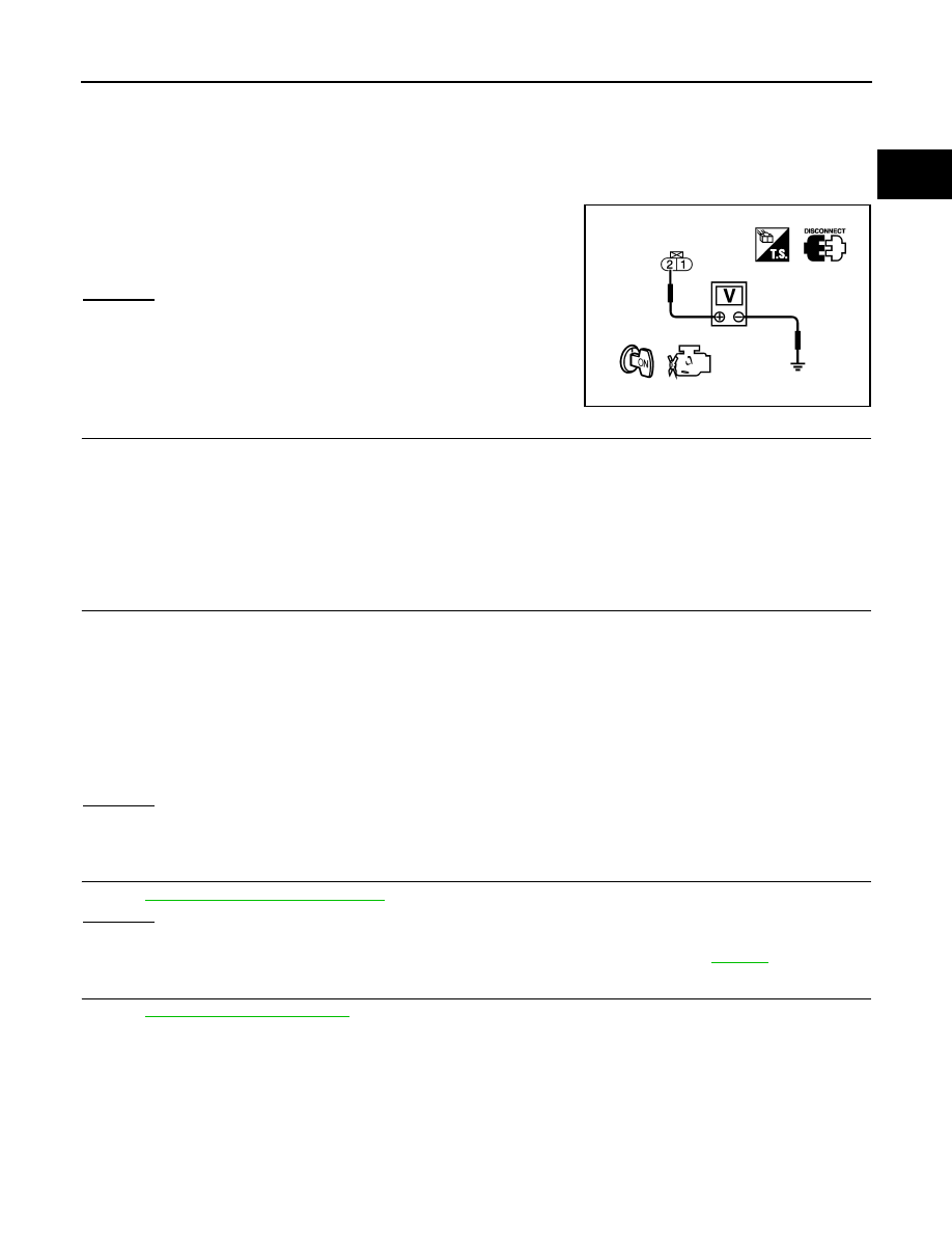
3. Turn ignition switch ON.

4. Check voltage between intake valve timing control solenoid

valve terminal 2 and ground with CONSULT or tester.

OK or NG

OK

>> GO TO 3.

NG

>> GO TO 2.

2.

DETECT MALFUNCTIONING PART

Check the following.

• Harness connectors E2, F32

• IPDM E/R harness connector E119

• Harness for open or short between intake valve timing control solenoid valve and IPDM E/R

>> Repair open circuit or short to ground or short to power in harness or connectors.

3.

CHECK INTAKE VALVE TIMING CONTROL SOLENOID VALVE OUTPUT SIGNAL CIRCUIT FOR OPEN

AND SHORT

1. Turn ignition switch OFF.

2. Disconnect ECM harness connector.

3. Check harness continuity between the following;

ECM terminal 10 and intake valve timing control solenoid valve (bank 1) terminal 1 or

ECM terminal 11 and intake valve timing control solenoid valve (bank 2) terminal 1.

Refer to Wiring Diagram.

4. Also check harness for short to ground and short to power. 
OK or NG

OK

>> GO TO 4.

NG

>> Repair open circuit or short to ground or short to power in harness or connectors.

4.

CHECK INTAKE VALVE TIMING CONTROL SOLENOID VALVE

Refer to 

EC-641, "Component Inspection"

.

OK or NG

OK

>> GO TO 5.

NG

>> Replace malfunctioning intake valve timing control solenoid valve. Refer to 

EM-193

.

5.

CHECK INTERMITTENT INCIDENT

Refer to 

GI-37, "Intermittent Incident"

.

>>

INSPECTION END

Component Inspection

INFOID:0000000007358498

INTAKE VALVE TIMING CONTROL SOLENOID VALVE

1. Disconnect intake valve timing control solenoid valve harness connector.

1.

Intake valve timing control position 
sensor (bank 2)

2.

Intake valve timing control solenoid 
valve (bank 2)

3.

Drive belt

4.

Radiator hose

5.

Intake valve timing control solenoid 
valve (bank 1)

6.

Intake valve timing control position 
sensor (bank 1)

Voltage: Battery voltage

PBIB0192E

Continuity should exist.

August 2012

2012 Pathfinder

EC-642

< DTC/CIRCUIT DIAGNOSIS >

[VK56DE]

P0075, P0081 IVT CONTROL SOLENOID VALVE

2. Check resistance between intake valve timing control solenoid

valve terminals as per the following.

If NG, replace intake valve timing control solenoid valve. Refer to

EM-193

.

If OK, go to next step.

3. Remove intake valve timing control solenoid valve. Refer to 

EM-

193

.

4. Provide 12 V DC between intake valve timing control solenoid

valve terminals and then interrupt it. Check that the plunger

moves as shown in the figure.

CAUTION:

Never apply 12 V DC continuously for 5 seconds or more.

Doing so may result in damage to the coil in intake valve

timing control solenoid valve.

If NG, replace intake valve timing control solenoid valve. Refer to

EM-193

.

NOTE:

Always replace O-ring when intake valve timing control

solenoid valve is removed.

Terminals

Resistance [at 20

°

C (68

°

F)]

1 and 2

7.1 - 7.7 

1 or 2 and ground


(Continuity should not exist)

PBIB0193E

PBIB2275E

August 2012

2012 Pathfinder

P0101 MAF SENSOR

EC-643

< DTC/CIRCUIT DIAGNOSIS >

[VK56DE]

C

D

E

F

G

H

I

J

K

L

M

A

EC

N

P

O

P0101 MAF SENSOR

Component Description

INFOID:0000000007358499

The mass air flow sensor is placed in the stream of intake air. It mea-

sures the intake flow rate by measuring a part of the entire intake

flow. The mass air flow sensor controls the temperature of the hot

wire to a certain amount. The heat generated by the hot wire is

reduced as the intake air flows around it. The greater air flow, the

greater the heat loss.

Therefore, the electric current supplied to the hot wire is changed to

maintain the temperature of the hot wire as air flow increases. The

ECM detects the air flow by means of this current change.

DTC Logic

INFOID:0000000007358500

DTC DETECTION LOGIC

NOTE:

If DTC P0101 is displayed with other DTC, first perform the trouble diagnosis for other DTC.

DTC CONFIRMATION PROCEDURE

1.

PRECONDITIONING

If DTC CONFIRMATION PROCEDURE has been previously conducted, always perform the following proce-

dure before conducting the next test.

1. Turn ignition switch OFF and wait at least 10 seconds.

2. Turn ignition switch ON.

3. Turn ignition switch OFF and wait at least 10 seconds.

>> GO TO 2.

2.

PERFORM DTC CONFIRMATION PROCEDURE

1. Start engine and warm it up to normal operating temperature.

2. Drive the vehicle for at least 5 seconds under the following conditions:

CAUTION:

Always drive vehicle at safe speed.

NOTE:

• The gear must be fixed while driving the vehicle.

• Keep the accelerator pedal as steady as possible during cruising.

3. Check 1st trip DTC.
Is 1st trip DTC detected?

YES

>> Proceed to 

EC-644, "Diagnosis Procedure"

.

NO

>> INSPECTION END

BBIA0355E

DTC No.

Trouble diagnosis

(Trouble diagnosis content)

DTC detecting condition

Possible cause

P0101

MAF SEN/CIRCUIT-B1
[Mass air flow (MAF) sensor cir-
cuit range/performance]

• A high voltage from the sensor is sent to 

ECM under light load driving condition.

• A low voltage from the sensor is sent to 

ECM under heavy load driving condition.

• Harness or connectors

(The sensor circuit is open or short-
ed.)

• Intake air leaks
• MAF sensor
• EVAP control system pressure sensor
• Intake air temperature sensor

Selector lever

Suitable position

Vehicle speed

40 km/h (25 MPH) or more

August 2012

2012 Pathfinder

EC-644

< DTC/CIRCUIT DIAGNOSIS >

[VK56DE]

P0101 MAF SENSOR

Diagnosis Procedure

INFOID:0000000007358501

1.

CHECK INTAKE SYSTEM

Check the following for connection.

• Air duct

• Vacuum hoses

• Intake air passage between air duct and intake manifold
Is the inspection result normal?

YES

>> GO TO 2.

NO

>> Reconnect the parts.

2.

CHECK GROUND CONNECTION

1. Turn ignition switch OFF.

2. Check ground connection E24. Refer to Ground Inspection in 

EC-623, "Ground Inspection"

.

Is the inspection result normal?

YES

>> GO TO 3.

NO

>> Repair or replace ground connection.

3.

CHECK MASS AIR FLOW (MAF) SENSOR POWER SUPPLY CIRCUIT

1. Disconnect MAF sensor harness connector.

2. Turn ignition switch ON.

3. Check the voltage between MAF sensor harness connector and ground.

Is the inspection result normal?

YES

>> GO TO 5.

NO

>> GO TO 4.

4.

DETECT MALFUNCTIONING PART

Check the following.

• Harness connectors E2, F32

• Harness for open or short between mass air flow sensor and IPDM E/R

>> Repair open circuit or short to ground or short to power in harness or connectors.

5.

CHECK MAF SENSOR GROUND CIRCUIT FOR OPEN AND SHORT

1. Turn ignition switch OFF.

2. Disconnect ECM harness connector.

3. Check the continuity between MAF sensor harness connector and ECM harness connector.

4. Also check harness for short to ground and short to power.
Is the inspection result normal?

YES

>> GO TO 6.

NO

>> Repair open circuit or short to ground or short to power in harness or connectors.

6.

CHECK MAF SENSOR INPUT SIGNAL CIRCUIT FOR OPEN AND SHORT

1. Check the continuity between MAF sensor harness connector and ECM harness connector.

MAF sensor

Ground

Voltage

Connector

Terminal

F53

2

Ground

Battery voltage

MAF sensor

ECM

Continuity

Connector

Terminal

Connector

Terminal

F53

3

F79

67

Existed

August 2012

2012 Pathfinder

P0101 MAF SENSOR

EC-645

< DTC/CIRCUIT DIAGNOSIS >

[VK56DE]

C

D

E

F

G

H

I

J

K

L

M

A

EC

N

P

O

2. Also check harness for short to ground and short to power.
Is the inspection result normal?

YES

>> GO TO 7.

NO

>> Repair open circuit or short to ground or short to power in harness or connectors.

7.

CHECK INTAKE AIR TEMPERATURE SENSOR

Check intake air temperature sensor. Refer to 

EC-656, "Component Inspection"

.

Is the inspection result normal?

YES

>> GO TO 8.

NO

>> Replace MAF sensor (with intake air temperature sensor). Refer to 

EM-164

.

8.

CHECK EVAP CONTROL SYSTEM PRESSURE SENSOR

Check EVAP control system pressure sensor. Refer to 

EC-788, "Component Inspection"

.

Is the inspection result normal?

YES

>> GO TO 9.

NO

>> Replace EVAP control system pressure sensor. Refer to 

FL-16, "Removal and Installation"

.

9.

CHECK MAF SENSOR

Check MAF sensor. Refer to 

EC-645, "Component Inspection"

.

Is the inspection result normal?

YES

>> GO TO 10.

NO

>> Replace MAF sensor. Refer to 

EM-164

.

10.

CHECK INTERMITTENT INCIDENT

Check intermittent incident. Refer to 

GI-37, "Intermittent Incident"

.

>> INSPECTION END

Component Inspection

INFOID:0000000007358502

MASS AIR FLOW SENSOR

 With CONSULT

1. Reconnect all harness connectors disconnected.
2. Start engine and warm it up to normal operating temperature.
3. Connect CONSULT and select “DATA MONITOR” mode.
4. Select “MAS A/F SE-B1” and check indication under the following conditions.

*: Check for linear voltage rise in response to engine being increased to approximately 4,000 rpm.

5. If the voltage is out of specification, proceed the following.
a. Check for the cause of uneven air flow through mass air flow sensor. Refer to the following.

• Crushed air ducts

• Malfunctioning seal of air cleaner element

MAF sensor

ECM

Continuity

Connector

Terminal

Connector

Terminal

F53

4

F79

51

Existed

Condition

MAS A/F SE-B1 (V)

Ignition switch ON (Engine stopped.)

Approx. 0.4

Idle (Engine is warmed-up to normal 
operating temperature.)

1.0 - 1.3

2,500 rpm (Engine is warmed-up to 
normal operating temperature.)

1.7 - 2.1

Idle to approximately 4,000 rpm

1.0 - 1.3 to Approx. 2.4*

August 2012

2012 Pathfinder

EC-646

< DTC/CIRCUIT DIAGNOSIS >

[VK56DE]

P0101 MAF SENSOR

• Uneven dirt of air cleaner element

• Improper specification of intake air system parts

b. If NG, repair or replace malfunctioning part and perform steps 2 to 4 again.

If OK, go to next step.

6. Turn ignition switch OFF.
7. Disconnect mass air flow sensor harness connector and reconnect it again.
8. Perform steps 2 to 4 again.
9. If NG, clean or replace mass air flow sensor. Refer to 

EM-164

.

 Without CONSULT

1. Reconnect all harness connectors disconnected.
2. Start engine and warm it up to normal operating temperature.
3. Check voltage between ECM terminal 51 (Mass air flow sensor

signal) and ground.

*: Check for linear voltage rise in response to engine being increased to approximately 4,000 rpm.

4. If the voltage is out of specification, proceed the following.
a. Check for the cause of uneven air flow through mass air flow sensor. Refer to the following.

• Crushed air ducts

• Malfunctioning seal of air cleaner element

• Uneven dirt of air cleaner element

• Improper specification of intake air system parts

b. If NG, repair or replace malfunctioning part and perform steps 2 and 3 again.

If OK, go to next step.

5. Turn ignition switch OFF.
6. Disconnect mass air flow sensor harness connector and reconnect it again.
7. Perform steps 2 and 3 again.
8. If NG, clean or replace mass air flow sensor. Refer to 

EM-164

.

Condition

MAS A/F SE-B1 (V)

Ignition switch ON (Engine stopped.)

Approx. 0.4

Idle (Engine is warmed-up to normal 
operating temperature.)

1.0 - 1.3

2,500 rpm (Engine is warmed-up to 
normal operating temperature.)

1.7 - 2.1

Idle to approximately 4,000 rpm

1.0 - 1.3 to Approx. 2.4*

PBIB1106E

August 2012

2012 Pathfinder

P0102, P0103 MAF SENSOR

EC-647

< DTC/CIRCUIT DIAGNOSIS >

[VK56DE]

C

D

E

F

G

H

I

J

K

L

M

A

EC

N

P

O

P0102, P0103 MAF SENSOR

Component Description

INFOID:0000000007358503

The mass air flow sensor is placed in the stream of intake air. It mea-

sures the intake flow rate by measuring a part of the entire intake

flow. The mass air flow sensor controls the temperature of the hot

wire to a certain amount. The heat generated by the hot wire is

reduced as the intake air flows around it. The greater air flow, the

greater the heat loss.

Therefore, the electric current supplied to the hot wire is changed to

maintain the temperature of the hot wire as air flow increases. The

ECM detects the air flow by means of this current change.

On Board Diagnosis Logic

INFOID:0000000007358504

These self-diagnoses have the one trip detection logic.

FAIL-SAFE MODE

When the malfunction is detected, the ECM enters fail-safe mode and the MIL illuminates.

DTC Confirmation Procedure

INFOID:0000000007358505

NOTE:

If DTC Confirmation Procedure has been previously conducted, always perform the following procedure

before conducting the next step.

1. Turn ignition switch OFF and wait at least 10 seconds.

2. Turn ignition switch ON.

3. Turn ignition switch OFF and wait at least 10 seconds.

PROCEDURE FOR DTC P0102

1. Start engine and wait at least 5 seconds.

2. Check DTC.

3. If DTC is detected, go to 

EC-648, "Diagnosis Procedure"

.

PROCEDURE FOR DTC P0103

1. Turn ignition switch ON.

2. Wait at least 5 seconds.

3. Check DTC.

4. If DTC is detected, go to 

EC-648, "Diagnosis Procedure"

.

If DTC is not detected, go to next step.

5. Start engine and wait at least 5 seconds.

6. Check DTC.

7. If DTC is detected, go to 

EC-648, "Diagnosis Procedure"

.

BBIA0355E

DTC No.

Trouble diagnosis name

DTC detecting condition

Possible cause

P0102
0102

Mass air flow sensor circuit 
low input

An excessively low voltage from the sensor is 
sent to ECM.

• Harness or connectors

(The sensor circuit is open or shorted.)

• Intake air leakage
• Mass air flow sensor

P0103
0103

Mass air flow sensor circuit 
high input

An excessively high voltage from the sensor is 
sent to ECM.

• Harness or connectors

(The sensor circuit is open or shorted.)

• Mass air flow sensor

Detected items

Engine operating condition in fail-safe mode

Mass air flow sensor circuit

Engine speed will not rise more than 2,400 rpm due to the fuel cut.

August 2012

2012 Pathfinder

EC-648

< DTC/CIRCUIT DIAGNOSIS >

[VK56DE]

P0102, P0103 MAF SENSOR

Diagnosis Procedure

INFOID:0000000007358506

1.

INSPECTION START

Which malfunction (P0102 or P0103) is duplicated?
P0102 or P0103

P0102 >> GO TO 2.

P0103 >> GO TO 3.

2.

CHECK INTAKE SYSTEM

Check the following for connection.

• Air duct

• Vacuum hoses

• Intake air passage between air duct to intake manifold
OK or NG

OK

>> GO TO 3.

NG

>> Reconnect the parts.

3.

RETIGHTEN GROUND SCREWS

1. Turn ignition switch OFF.

2. Loosen and retighten ground screws on the body.

Refer to 

EC-623, "Ground Inspection"

.

OK or NG

OK

>> GO TO 4.

NG

>> Repair or replace ground connections.

4.

CHECK MASS AIR FLOW SENSOR POWER SUPPLY CIRCUIT

1. Disconnect mass air flow (MAF) sensor (1) harness connector.
-

: Vehicle front

2. Turn ignition switch ON.

BBIA0539E

ALBIA0353ZZ

August 2012

2012 Pathfinder


Content      ..     318      319      320      321     ..