Nissan Pathfinder (2012 year). Manual - part 281
P1550 BATTERY CURRENT SENSOR
EC-329
< DTC/CIRCUIT DIAGNOSIS >
[VQ40DE]
C
D
E
F
G
H
I
J
K
L
M
A
EC
N
P
O
OK or NG
OK
>> GO TO 2.
NG
>> Repair or replace ground connections.
2.
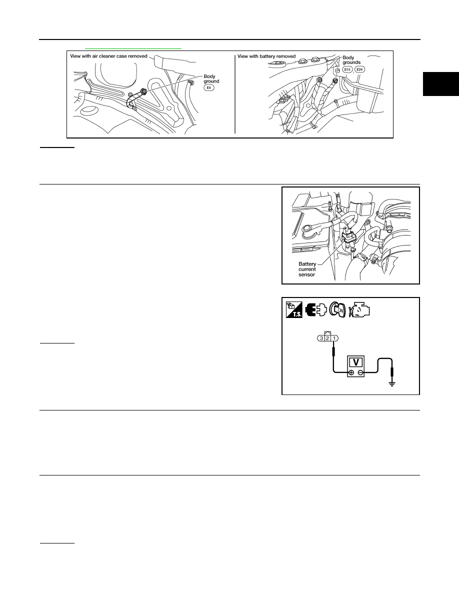
CHECK BATTERY CURRENT SENSOR POWER SUPPLY CIRCUIT
1. Disconnect battery current sensor harness connector.
2. Turn ignition switch ON.
3. Check voltage between battery current sensor terminal 1 and
ground with CONSULT or tester.
OK or NG
OK
>> GO TO 4.
NG
>> GO TO 3.
3.
DETECT MALFUNCTIONING PART
Check the following.
• Harness connectors E5, F14
• Harness for open or short between battery current sensor and ECM
>> Repair open circuit or short to ground or short to power in harness or connectors.
4.
CHECK BATTERY CURRENT SENSOR GROUND CIRCUIT FOR OPEN AND SHORT
1. Turn ignition switch OFF.
2. Disconnect ECM harness connector.
3. Check harness continuity between battery current sensor terminal 2 and ECM terminal 67.
4. Also check harness for short to ground and short to power.
OK or NG
OK
>> GO TO 6.
NG
>> GO TO 5.
BBIA0539E
BBIA0582E
Voltage: Approximately 5V
PBIB2609E
Continuity should exist.
August 2012
2012 Pathfinder