Nissan Pathfinder (2012 year). Manual - part 280


  Index      Manuals     Nissan Pathfinder (2012 year) - Service and Repair Manual


Search            copyright infringement  


Content      ..     278      279      280      281     ..


Nissan Pathfinder (2012 year). Manual - part 280


P1217 ENGINE OVER TEMPERATURE

EC-321

< DTC/CIRCUIT DIAGNOSIS >

[VQ40DE]

C

D

E

F

G

H

I

J

K

L

M

A

EC

N

P

O

5. If the results are NG, go to 

EC-321, "Diagnosis Procedure"

.

 WITH GST

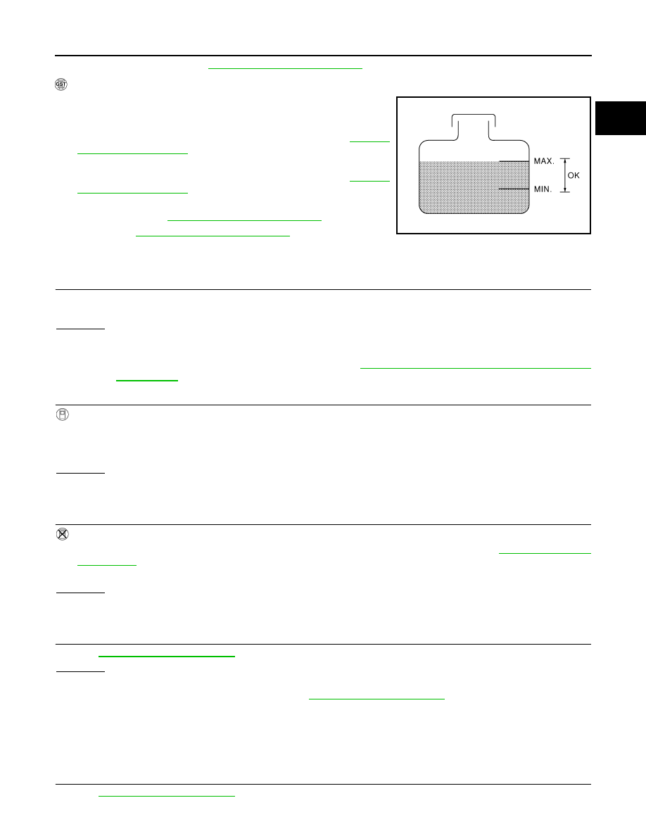
1. Check the coolant level in the reservoir tank and radiator.

Allow engine to cool before checking coolant level.

If the coolant level in the reservoir tank and/or radiator is below

the proper range, skip the following steps and go to 

EC-321,

"Diagnosis Procedure"

.

2. Confirm whether customer filled the coolant or not. If customer

filled the coolant, skip the following steps and go to 

EC-321,

"Diagnosis Procedure"

.

3. Perform IPDM E/R auto active test and check cooling fan motor

operation, refer to 

EC-321, "Diagnosis Procedure"

.

4. If NG, go to 

EC-321, "Diagnosis Procedure"

.

Diagnosis Procedure

INFOID:0000000007358264

1.

CHECK COOLING FAN (CRANKSHAFT DRIVEN) OPERATION

1. Start engine and let it idle.

2. Make sure that cooling fan (crankshaft driven) operates normally.
OK or NG

OK (With CONSULT)>>GO TO 2.

OK (Without CONSULT)>>GO TO 3.

NG

>> Check cooling fan (crankshaft driven). Refer to 

CO-20, "Removal and Installation (Crankshaft

driven type)"


2.

CHECK COOLING FAN OPERATION


With CONSULT

1. Start engine and let it idle.

2. Select “COOLING FAN” in “ACTIVE TEST” mode with CONSULT.

3. Make sure that cooling fan operates at each speed (LOW/HI).
OK or NG

OK

>> GO TO 4.

NG

>> Check cooling fan control circuit. (Go to "PROCEDURE A".)

3.

CHECK COOLING FAN OPERATION


Without CONSULT

1. Perform IPDM E/R auto active test and check cooling fan motors operation, refer to 

PCS-9, "Diagnosis

Description"

.

2. Make sure that cooling fan operates at each speed (Low/High).
OK or NG

OK

>> GO TO 4.

NG

>> Check cooling fan control circuit. (Go to "PROCEDURE A".)

4.

CHECK COOLING SYSTEM FOR LEAK

Refer to 

CO-11, "System Inspection"

.

OK or NG

OK

>> GO TO 5.

NG

>> Check the following for leak. Refer to 

CO-11, "System Inspection"

.

• Hose

• Radiator

• Radiator cap

• Reservoir tank

• Water pump

5.

CHECK RESERVOIR TANK CAP

Refer to 

CO-11, "System Inspection"

.

SEF621W

August 2012

2012 Pathfinder

EC-322

< DTC/CIRCUIT DIAGNOSIS >

[VQ40DE]

P1217 ENGINE OVER TEMPERATURE

OK or NG

OK

>> GO TO 6.

NG

>> Replace reservoir tank cap. Refer to 

CO-17, "Exploded View"

.

6.

CHECK COMPONENT PARTS

Check the following

• Thermostat. Refer to 

CO-28, "Removal and Installation"

.

• Engine coolant temperature sensor. Refer to 

EC-134, "Component Inspection"

.

OK or NG

OK

>> GO TO 7.

NG

>> Replace malfunctioning component.

7.

CHECK MAIN 12 CAUSES

If the cause cannot be isolated, go to 

EC-322, "Main 12 Causes of Overheating"

.

>>

INSPECTION END

Main 12 Causes of Overheating

INFOID:0000000007358265

*1: Turn the ignition switch ON.
*2: Engine running at 3,000 rpm for 10 minutes.

Engine

Step

Inspection item

Equipment

Standard

Reference page

OFF

1

• Blocked radiator
• Blocked condenser
• Blocked radiator grille
• Blocked bumper

• Visual

No blocking

2

• Coolant mixture

• Coolant tester

CO-12, "Changing Engine Coolant"

3

• Coolant level

• Visual

Coolant up to MAX level in 
reservoir tank and radiator 
filler neck

CO-12, "Changing Engine 
Coolant"

4

• Reservoir tank cap

• Pressure tester

59 - 98 kPa
(0.6 - 1.0 kg/cm

2

, 9 - 14 

psi) (Limit)

CO-11, "System Inspec-
tion"

ON*

2

5

• Coolant leaks

• Visual

No leaks

CO-11, "System Inspec-
tion"

ON*

2

6

• Thermostat

• Touch the upper and 

lower radiator hoses

Both hoses should be hot

CO-28, "Removal and In-
stallation"

ON*

1

7

• Cooling fan

• CONSULT

Operating

See trouble diagnosis for 
DTC P1217 (

EC-398, "Di-

agnosis Procedure"

).

ON*

2

7

• Cooling fan (Crankshaft 

driven)

• Visual

Operating

See 

CO-20, "Removal 

and Installation (Crank-
shaft driven type)"

.

OFF

8

• Combustion gas leak

• Color checker chemical 

tester 4 Gas analyzer

Negative

ON*

3

9

• Coolant temperature 

gauge

• Visual

Gauge less than 3/4 when 
driving

• Coolant overflow to res-

ervoir tank

• Visual

No overflow during driving 
and idling

CO-12, "Changing Engine 
Coolant"

OFF*

4

10

• Coolant return from res-

ervoir tank to radiator

• Visual

Should be initial level in 
reservoir tank

CO-12, "Changing Engine 
Coolant"

OFF

11

• Cylinder head

• Straight gauge feeler 

gauge

0.1 mm (0.004 in) Maxi-
mum distortion (warping)

EM-96, "Inspection After 
Disassembly"

12

• Cylinder block and pis-

tons

• Visual

No scuffing on cylinder 
walls or piston

EM-96, "Inspection After 
Disassembly"

August 2012

2012 Pathfinder

P1217 ENGINE OVER TEMPERATURE

EC-323

< DTC/CIRCUIT DIAGNOSIS >

[VQ40DE]

C

D

E

F

G

H

I

J

K

L

M

A

EC

N

P

O

*3: Drive at 90 km/h (55 MPH) for 30 minutes and then let idle for 10 minutes.
*4: After 60 minutes of cool down time.
For more information, refer to 

CO-9, "Troubleshooting Chart"

August 2012

2012 Pathfinder

EC-324

< DTC/CIRCUIT DIAGNOSIS >

[VQ40DE]

P1225 TP SENSOR

P1225 TP SENSOR

Component Description

INFOID:0000000007358266

Electric throttle control actuator consists of throttle control motor,

throttle position sensor, etc. The throttle position sensor responds to

the throttle valve movement. 

The throttle position sensor has the two sensors. These sensors are

a kind of potentiometers which transform the throttle valve position

into output voltage, and emit the voltage signal to the ECM. In addi-

tion, these sensors detect the opening and closing speed of the

throttle valve and feed the voltage signals to the ECM. The ECM

judges the current opening angle of the throttle valve from these sig-

nals and the ECM controls the throttle control motor to make the

throttle valve opening angle properly in response to driving condi-

tion.

On Board Diagnosis Logic

INFOID:0000000007358267

The MIL will not illuminate for this diagnosis.

DTC Confirmation Procedure

INFOID:0000000007358268

NOTE:

If DTC Confirmation Procedure has been previously conducted, always perform the following before conduct-

ing the next step.

1. Turn ignition switch OFF and wait at least 10 seconds.

2. Turn ignition switch ON.

3. Turn ignition switch OFF and wait at least 10 seconds.

TESTING CONDITION:

Before performing the following procedure, confirm that battery voltage is more than 10V at idle.

1. Turn ignition switch ON.
2. Turn ignition switch OFF and wait at least 10 seconds.
3. Turn ignition switch ON.
4. Check 1st trip DTC.
5. If 1st trip DTC is detected, go to 

EC-324, "Diagnosis Procedure"

.

Diagnosis Procedure

INFOID:0000000007358269

1.

CHECK ELECTRIC THROTTLE CONTROL ACTUATOR VISUALLY

1. Turn ignition switch OFF.

2. Remove the intake air duct. Refer to 

EM-26, "Removal and Installation"

.

3. Check if foreign matter is caught between the throttle valve and

the housing.

OK or NG

OK

>> GO TO 2.

NG

>> Remove the foreign matter and clean the electric throttle

control actuator inside, and then perform throttle valve

closed position learning. Refer to 

EC-25, "Throttle Valve

Closed Position Learning"

.

2.

REPLACE ELECTRIC THROTTLE CONTROL ACTUATOR

PBIB0145E

DTC No.

Trouble diagnosis name

DTC detecting condition

Possible cause

P1225
1225

Closed throttle position 
learning performance

Closed throttle position learning value is exces-
sively low.

• Electric throttle control actuator

(TP sensor 1 and 2)

BBIA0554E

August 2012

2012 Pathfinder

P1225 TP SENSOR

EC-325

< DTC/CIRCUIT DIAGNOSIS >

[VQ40DE]

C

D

E

F

G

H

I

J

K

L

M

A

EC

N

P

O

Replace the electric throttle control actuator. Refer to 

EM-27, "Removal and Installation"

.

>>

INSPECTION END

August 2012

2012 Pathfinder

EC-326

< DTC/CIRCUIT DIAGNOSIS >

[VQ40DE]

P1226 TP SENSOR

P1226 TP SENSOR

Component Description

INFOID:0000000007358270

Electric throttle control actuator consists of throttle control motor,

throttle position sensor, etc. The throttle position sensor responds to

the throttle valve movement. 

The throttle position sensor has the two sensors. These sensors are

a kind of potentiometers which transform the throttle valve position

into output voltage, and emit the voltage signal to the ECM. In addi-

tion, these sensors detect the opening and closing speed of the

throttle valve and feed the voltage signals to the ECM. The ECM

judges the current opening angle of the throttle valve from these sig-

nals and the ECM controls the throttle control motor to make the

throttle valve opening angle properly in response to driving condi-

tion.

On Board Diagnosis Logic

INFOID:0000000007358271

The MIL will not illuminate for this diagnosis.

DTC Confirmation Procedure

INFOID:0000000007358272

NOTE:

If DTC Confirmation Procedure has been previously conducted, always perform the following before conduct-

ing the next step.

1. Turn ignition switch OFF and wait at least 10 seconds.

2. Turn ignition switch ON.

3. Turn ignition switch OFF and wait at least 10 seconds.

TESTING CONDITION:

Before performing the following procedure, confirm that battery voltage is more than 10V at idle.

1. Turn ignition switch ON.
2. Turn ignition switch OFF and wait at least 10 seconds.
3. Turn ignition switch ON.
4. Repeat steps 2 and 3 for 32 times.
5. Check 1st trip DTC.
6. If 1st trip DTC is detected, go to 

EC-326, "Diagnosis Procedure"

.

Diagnosis Procedure

INFOID:0000000007358273

1.

CHECK ELECTRIC THROTTLE CONTROL ACTUATOR VISUALLY

1. Turn ignition switch OFF.

2. Remove the intake air duct. Refer to 

EM-26, "Removal and Installation"

.

3. Check if foreign matter is caught between the throttle valve and

the housing.

OK or NG

OK

>> GO TO 2.

NG

>> Remove the foreign matter and clean the electric throttle

control actuator inside, and then perform throttle valve

closed position learning. Refer to 

EC-25, "Throttle Valve

Closed Position Learning"

.

PBIB0145E

DTC No.

Trouble diagnosis name

DTC detecting condition

Possible cause

P1226
1226

Closed throttle position 
learning performance 

Closed throttle position learning is not per-
formed successfully, repeatedly.

• Electric throttle control actuator

(TP sensor 1 and 2)

BBIA0554E

August 2012

2012 Pathfinder

P1226 TP SENSOR

EC-327

< DTC/CIRCUIT DIAGNOSIS >

[VQ40DE]

C

D

E

F

G

H

I

J

K

L

M

A

EC

N

P

O

2.

REPLACE ELECTRIC THROTTLE CONTROL ACTUATOR

Replace the electric throttle control actuator. Refer to 

EM-27, "Removal and Installation"

.

>>

INSPECTION END

August 2012

2012 Pathfinder

EC-328

< DTC/CIRCUIT DIAGNOSIS >

[VQ40DE]

P1550 BATTERY CURRENT SENSOR

P1550 BATTERY CURRENT SENSOR

Component Description

INFOID:0000000007358274

The power generation voltage variable control enables fuel con-

sumption to be decreased by reducing the engine load which is

caused by the power generation of the generator. The battery cur-

rent sensor is installed to the battery cable at the negative terminal.

The sensor measures the charging/discharging current of the bat-

tery. Based on the sensor signal, ECM judges whether or not the

power generation voltage variable control is performed. When per-

forming the power generation voltage variable control, ECM calcu-

lates the target power generation voltage based on the sensor

signal. And ECM sends the calculated value as the power genera-

tion command value to IPDM E/R. For the details of the power gen-

eration voltage variable control, refer to 

CHG-12, "System

Description"

.

CAUTION:

Never connect the electrical component or the ground wire directly to the battery terminal.The con-

nection causes the malfunction of the power generation voltage variable control, and then battery dis-

charge may occur.

On Board Diagnosis Logic

INFOID:0000000007358275

The MIL will not illuminate for this diagnosis.

NOTE:

If DTC P1550 is displayed with DTC P0643, first perform the trouble diagnosis for DTC P0643. Refer to

EC-312

.

DTC Confirmation Procedure

INFOID:0000000007358276

NOTE:

If DTC Confirmation Procedure has been previously conducted, always perform the following before conduct-

ing the next step.

1. Turn ignition switch OFF and wait at least 10 seconds.

2. Turn ignition switch ON.

3. Turn ignition switch OFF and wait at least 10 seconds.

TESTING CONDITION:

Before performing the following procedure, confirm that battery voltage is more than 8V at idle.

1. Start engine and wait at least 10 seconds.
2. Check 1st trip DTC.
3. If 1st trip DTC is detected, go to 

EC-328, "Diagnosis Procedure"

.

Diagnosis Procedure

INFOID:0000000007358277

1.

CHECK GROUND CONNECTIONS

1. Turn ignition switch OFF.

2. Loosen and retighten three ground screws on the body.

BBIA0582E

DTC No.

Trouble diagnosis name

DTC detecting condition

Possible cause

P1550
1550

Battery current sensor circuit 
range/performance

The output voltage of the battery current 
sensor remains within the specified 
range while engine is running.

• Harness or connectors

(The sensor circuit is open or shorted.)

• Battery current sensor

August 2012

2012 Pathfinder


Content      ..     278      279      280      281     ..