Nissan Pathfinder (2012 year). Manual - part 223


  Index      Manuals     Nissan Pathfinder (2012 year) - Service and Repair Manual


Search            copyright infringement  


Content      ..     221      222      223      224     ..


Nissan Pathfinder (2012 year). Manual - part 223


PREPARATION

DLN-349

< PREPARATION >

[FRONT FINAL DRIVE: R180A]

C

E

F

G

H

I

J

K

L

M

A

B

DLN

N

O

P

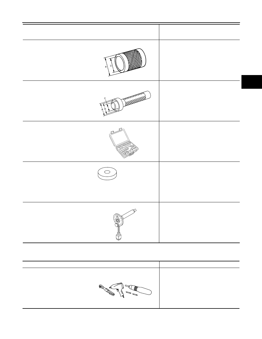
Commercial Service Tool

INFOID:0000000007357608

ST33200000
(J-26082)
Drift

Installing drive pinion front bearing inner race

a: 60 mm (2.36 in) dia.
b: 44.5 mm (1.752 in) dia.

ST33230000
(J-35867)
Drift

Installing side bearing inner race

a: 51 mm (2.01 in) dia.
b: 41 mm (1.61 in) dia.
c: 28 mm (1.10 in) dia.

(

)

(J-34309)
Differential shim selector tool

Adjusting bearing preload and drive pinion 
height

(

)

(J-25269-18)
Side bearing disc (2 Req'd) 

Selecting drive pinion height adjusting washer

KV10112100
(BT-8653-A)
Angle wrench

Tightening bolts for drive gear

Tool number
(Kent-Moore No.)
Tool name

Description

ZZA1002D

ZZA1046D

NT134

NT135

NT014

Tool name

Description

Power tool

Loosening nuts, screws and bolts

PIIB1407E

August 2012

2012 Pathfinder

DLN-350

< SYSTEM DESCRIPTION >

[FRONT FINAL DRIVE: R180A]

NOISE, VIBRATION AND HARSHNESS (NVH) TROUBLESHOOTING

SYSTEM DESCRIPTION

NOISE, VIBRATION AND HARSHNESS (NVH) TROUBLESHOOTING

NVH Troubleshooting Chart

INFOID:0000000007357609

Use the chart below to help you find the cause of the symptom. If necessary, repair or replace these parts.

×

: Applicable

Reference page

DLN-360

DLN-360

DLN-360

DLN-360

DLN-360

DLN-352

DL

N-33

8, 

"NVH T

ro

ub

les

ho

ot

ing

 Cha

rt"

F

AX-5,

 "NVH T

rou

bl

es

ho

ot

in

g Cha

rt"

FSU-6,

 "NVH T

ro

ub

les

ho

ot

ing

 Ch

art"

WT

-4

8, 

"NVH T

rou

bl

es

ho

ot

ing

 Cha

rt"

WT

-4

8, 

"NVH T

rou

bl

es

ho

ot

ing

 Cha

rt"

RA

X-5, 

"NVH T

rou

bl

es

ho

ot

ing

 Cha

rt"

BR-6, 

"NVH T

rou

bl

es

ho

oti

ng

 Cha

rt"

ST

-1

1,

 "NVH T

rou

bl

es

ho

ot

in

C

h

ar

t"

Possible cause and SUSPECTED PARTS

G

e

ar t

oo

th 

rou

gh

Gea

r co

nt

ac

t i

mp

rop

er

To

ot

h s

u

rf

ac

es

 w

o

rn

Ba

ck

la

sh

 in

co

rrec

t

Co

mp

an

io

n f

lan

ge

 e

xc

es

si

ve

 run

ou

t

Gea

r oi

l i

mp

rop

er

PR

OP

EL

LE

R

 S

H

A

F

T

FRO

N

T A

X

L

E

F

R

ONT

 SUSPENSI

ON

TI

RE

S

ROAD W

H

EEL

DRIV

E SHAFT

BR

AK

E

S

S

T

EERING

Symptom

Noise

×

×

×

×

×

×

×

×

×

×

×

×

×

×

August 2012

2012 Pathfinder

DESCRIPTION

DLN-351

< SYSTEM DESCRIPTION >

[FRONT FINAL DRIVE: R180A]

C

E

F

G

H

I

J

K

L

M

A

B

DLN

N

O

P

DESCRIPTION

Cross-Sectional View

INFOID:0000000007357610

1.

Differential side shaft

2.

Differential side shaft bearing

3.

Side gear

4.

Drive gear

5.

Pinion mate shaft

6.

Differential case

7.

Side bearing

8.

Pinion mate gear

9.

Drive pinion

10. Collapsible spacer

11. Companion flange

12. Drive pinion front bearing

13. Drive pinion rear bearing

14. Housing spacer

PDIA0695E

August 2012

2012 Pathfinder

DLN-352

< PERIODIC MAINTENANCE >

[FRONT FINAL DRIVE: R180A]

DIFFERENTIAL GEAR OIL

PERIODIC MAINTENANCE

DIFFERENTIAL GEAR OIL

Changing Differential Gear Oil

INFOID:0000000007357611

DRAINING

1. Stop the engine.
2. Remove the drain plug and gasket from the front final drive

assembly to drain the differential gear oil.

3. Install the drain plug with a new gasket to the front final drive

assembly. Tighten to the specified torque. Refer to 

DLN-360,

"Disassembly and Assembly"

.

CAUTION:

Do not reuse gasket.

FILLING

1. Remove the filler plug and gasket from the front final drive

assembly.

2. Fill the front final drive assembly with new differential gear oil

until the level reaches the specified level near the filler plug hole.

3. Install the filler plug with a new gasket on it to the front final drive assembly. Tighten to the specified

torque. Refer to 

DLN-360, "Disassembly and Assembly"

.

CAUTION:

Do not reuse gasket.

Checking Differential Gear Oil

INFOID:0000000007357612

DIFFERENTIAL GEAR OIL LEAKAGE AND LEVEL

1. Make sure that differential gear oil is not leaking from the front final drive assembly or around it.
2. Check the differential gear oil level from the filler plug hole as

shown.

CAUTION:

Do not start engine while checking differential gear oil level.

3. Install the filler plug with a new gasket on it to the front final drive

assembly. Tighten to the specified torque. Refer to 

DLN-360,

"Disassembly and Assembly"

.

CAUTION:

Do not reuse gasket.

LDIA0175E

Differential gear oil 
grade and capacity

: Refer to 

MA-18, "FOR USA 

AND CANADA : Fluids and 
Lubricants"

 (United States 

and Canada), 

MA-20, "FOR 

MEXICO : Fluids and Lubri-
cants"

 (Mexico).

LDIA0176E

LDIA0176E

August 2012

2012 Pathfinder

FRONT OIL SEAL

DLN-353

< REMOVAL AND INSTALLATION >

[FRONT FINAL DRIVE: R180A]

C

E

F

G

H

I

J

K

L

M

A

B

DLN

N

O

P

REMOVAL AND INSTALLATION

FRONT OIL SEAL

Removal and Installation

INFOID:0000000007357613

NOTE:

When removing components such as hoses, tubes/lines, etc., cap or plug openings to prevent fluid from spill-

ing.

REMOVAL

1. Remove the drive shafts from the front final drive assembly. Refer to 

RAX-8, "Removal and Installation"

.

2. Remove the front propeller shaft from the front final drive assembly. Refer to 

DLN-319, "Removal and

Installation"

.

3. Measure the total preload torque. Refer to 

DLN-360, "Disassembly and Assembly"

.

NOTE:

Record the total preload torque measurement.

4. Remove the drive pinion lock nut using suitable tool.
5. Put matching marks on the companion flange and drive pinion

using paint.

CAUTION:

Use paint to make the matching marks. Do not damage the

companion flange or drive pinion.

6. Remove the companion flange using suitable tool.

7. Remove the front oil seal using Tool.

INSTALLATION

BDIA0001E

LDIA0171E

Tool number

: ST33290001 (J-34286)

LDIA0172E

August 2012

2012 Pathfinder

DLN-354

< REMOVAL AND INSTALLATION >

[FRONT FINAL DRIVE: R180A]

FRONT OIL SEAL

1. Apply multi-purpose grease to the lips and differential gear oil to

the circumference of the new front oil seal. Then drive the new

front oil seal in evenly until it becomes flush with the gear carrier

using Tools.

CAUTION:

• Do not reuse front oil seal.

• Do not incline the new front oil seal when installing.

• Apply multi-purpose grease to the lips and differential

gear oil to the circumference of the new front oil seal.

2. Install the companion flange to the drive pinion while aligning the matching marks.
3. Apply anti-corrosive oil to the threads of the drive pinion and the

seating surface of the new drive pinion lock nut. Then adjust the

drive pinion lock nut tightening torque using suitable tool (A),

and check the total preload torque using Tool (B).

• The total preload torque should be within the total preload

torque specification. When not replacing the collapsible

spacer, it should also be equal to the measurement taken dur-

ing removal plus an additional 0.56 N·m (0.06 Kg-m, 5 in-lb).

• If the total preload torque is low, tighten the drive pinion lock

nut in 6.8 N·m (0.69 Kg-m, 5ft-lb) increments until the total pre-

load torque is met.

CAUTION:

• Do not reuse drive pinion lock nut.

• Apply anti-corrosive oil to the threads of the drive pinion

and the seating surface of the new drive pinion lock nut.

• Adjust the drive pinion lock nut tightening torque to the

lower limit first. Do not exceed the drive pinion lock nut

specified torque. Refer to 

DLN-360, "Disassembly and

Assembly"

.

• Do not loosen drive pinion lock nut to adjust the total preload torque. If the drive pinion lock nut

torque or the total preload torque exceeds the specifications, replace the collapsible spacer and

tighten it again to adjust. Refer to 

DLN-360, "Disassembly and Assembly"

.

• After adjustment, rotate drive pinion back and forth 2 to 3 times to check for unusual noise, rota-

tion malfunction, and other malfunctions.

4. Install new side oil seals into the front final drive assembly. Refer to 

DLN-355, "Removal and Installation"

.

5. Installation of the remaining components is in the reverse order of removal.

CAUTION:

Check the differential gear oil level after installation. Refer to 

DLN-352, "Checking Differential Gear

Oil"

.

Tool number

(A): ST30720000 (J-25405)
(B): ST27863000 ( — )

WDIA0147E

Tool number

(B): ST3127S000 (J-25765-A)

Total preload torque: Refer to 

DLN-360, "Disassem-

bly and Assembly"

.

WDIA0381E

August 2012

2012 Pathfinder

SIDE OIL SEAL

DLN-355

< REMOVAL AND INSTALLATION >

[FRONT FINAL DRIVE: R180A]

C

E

F

G

H

I

J

K

L

M

A

B

DLN

N

O

P

SIDE OIL SEAL

Removal and Installation

INFOID:0000000007357614

REMOVAL

1. Remove the drive shafts from the front final drive assembly. Refer to 

FAX-7, "VQ40DE : Removal and

Installation"

.

2. Remove the side oil seal using suitable tool.

CAUTION:

Do not reuse the side oil seal.

INSTALLATION

1. Apply multi-purpose grease to the lips and differential gear oil to

the circumference of the new side oil seal. Then drive the new

side oil seal in evenly until it becomes flush with the gear carrier

using Tools.

CAUTION:

• Do not reuse side oil seal.

• Do not incline the new side oil seal when installing.

• Apply multi-purpose grease to the lips and differential

gear oil to the circumference of the new side oil seal.

2. Installation of the remaining components is in the reverse order of removal.

CAUTION:

Check the differential gear oil level after installation. Refer to 

DLN-352, "Checking Differential Gear

Oil"

.

LDIA0173E

Tool number

(A): ST30720000 (J-25405)
(B): ST27863000 ( — )

PDIA0826E

August 2012

2012 Pathfinder

DLN-356

< REMOVAL AND INSTALLATION >

[FRONT FINAL DRIVE: R180A]

CARRIER COVER

CARRIER COVER

Removal and Installation

INFOID:0000000007357615

REMOVAL

1. Drain the differential gear oil. Refer to 

DLN-352, "Changing Differential Gear Oil"

.

2. Remove the front final drive assembly. Refer to 

DLN-357, "Removal and Installation"

.

3. Remove the carrier cover bolts and separate the carrier cover

from the gear carrier using Tool.

CAUTION:

• Do not damage the mating surface.

• Do not insert flat-bladed screwdriver, this will damage the

mating surface.

INSTALLATION

1. Apply a 3 mm (0.12 in) bead of sealant to the mating surface of

the carrier cover as shown.

• Use Genuine Silicone RTV or equivalent. Refer to 

GI-14,

"Recommended Chemical Products and Sealants"

.

CAUTION:

Remove any old sealant adhering to the mating surfaces.

Also remove any moisture, oil, or foreign material adhering

to the application and mating surfaces.

2. Install the carrier cover to the gear carrier. Tighten the bolts to

the specified torque. Refer to 

DLN-360, "Disassembly and

Assembly"

.

3. Install the front final drive assembly. Refer to 

DLN-357,

"Removal and Installation"

.

CAUTION:

Fill the front final drive assembly with recommended differential gear oil. Refer to 

DLN-352

.

Tool number

: KV10111100 (J-37228)

PDIA0699E

PDIA0712E

August 2012

2012 Pathfinder


Content      ..     221      222      223      224     ..