Nissan Pathfinder (2012 year). Manual - part 221
SERVICE DATA AND SPECIFICATIONS (SDS)
DLN-333
< SERVICE DATA AND SPECIFICATIONS (SDS)
[PROPELLER SHAFT: 2S1330]
C
E
F
G
H
I
J
K
L
M
A
B
DLN
N
O
P
SERVICE DATA AND SPECIFICATIONS (SDS)
SERVICE DATA AND SPECIFICATIONS (SDS)
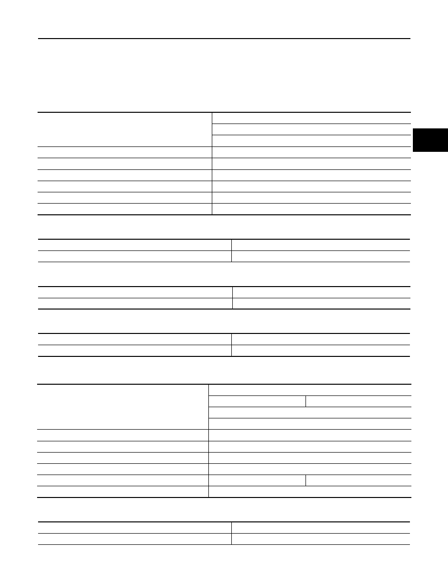
General Specification
INFOID:0000000007357593
2WD models
Unit: mm (in)
PROPELLER SHAFT RUNOUT
Unit: mm (in)
PROPELLER SHAFT JOINT FLEX EFFORT
Unit: N·m (kg-m, in-lb)
JOURNAL AXIAL PLAY
Unit: mm (in)
4WD models
Unit: mm (in)
PROPELLER SHAFT RUNOUT
Unit: mm (in)
PROPELLER SHAFT JOINT FLEX EFFORT
Applied model
2WD
VQ40DE
A/T
Propeller shaft model
2S1330 (aluminum tube)
Number of joints
2
Coupling method with rear final drive
Flange type
Coupling method with transmission
Sleeve type
Shaft length (Spider to spider)
1422.2
±
1.5 (55.99
±
0.06)
Shaft outer diameter
127.6 + 0.22 / - 0.29 (5.02
±
0.01)
Item
Limit
Propeller shaft runout
1.02 (0.0402)
Item
Limit
Propeller shaft joint flex effort
2.26 (0.23, 20) or less
Item
Limit
Journal axial play
0.02 (0.0008) or less
Applied model
4WD
Part time
Full time
VQ40DE
A/T
Propeller shaft model
2S1330 (steel tube)
Number of joints
2
Coupling method with front final drive
Flange type
Coupling method with transfer
Sleeve type
Shaft length (Spider to spider)
952.8
±
1.5 (37.51
±
0.06)
917.8
±
1.5 (36.13
±
0.06)
Shaft outer diameter
76.2 + 0.00 / - 0.13 (3.00 + 0.00/ - 0.01)
Item
Limit
Propeller shaft runout
0.6 (0.024)
August 2012
2012 Pathfinder