Nissan Pathfinder (2012 year). Manual - part 219
NOISE, VIBRATION, AND HARSHNESS (NVH) TROUBLESHOOTING
DLN-317
< SYSTEM DESCRIPTION >
[PROPELLER SHAFT: 2F1310]
C
E
F
G
H
I
J
K
L
M
A
B
DLN
N
O
P
SYSTEM DESCRIPTION
NOISE, VIBRATION, AND HARSHNESS (NVH) TROUBLESHOOTING
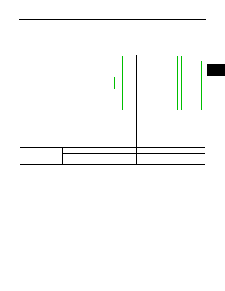
NVH Troubleshooting Chart
INFOID:0000000007357580
Use the chart below to help you find the cause of the symptom. If necessary, repair or replace these parts.
×
: Applicable
Reference page
"
Possible cause and suspected parts
Une
ven
rot
a
tion
torq
ue
Rot
ati
on
im
ba
la
nc
e
Ex
ce
ss
iv
e run
ou
t
Di
ffere
n
tial
Axle
Su
sp
en
si
on
Ti
re
s
Road wheel
Driv
e sh
af
t
Brak
es
S
tee
ring
Symptom
Noise
×
×
×
×
×
×
×
×
×
×
×
Shake
×
×
×
×
×
×
×
Vibration
×
×
×
×
×
×
×
×
August 2012
2012 Pathfinder