Nissan Pathfinder (2012 year). Manual - part 215


  Index      Manuals     Nissan Pathfinder (2012 year) - Service and Repair Manual


Search            copyright infringement  


Content      ..     213      214      215      216     ..


Nissan Pathfinder (2012 year). Manual - part 215


AIR BREATHER HOSE

DLN-285

< REMOVAL AND INSTALLATION >

[TRANSFER: TX15B]

C

E

F

G

H

I

J

K

L

M

A

B

DLN

N

O

P

AIR BREATHER HOSE

Removal and Installation

INFOID:0000000007357568
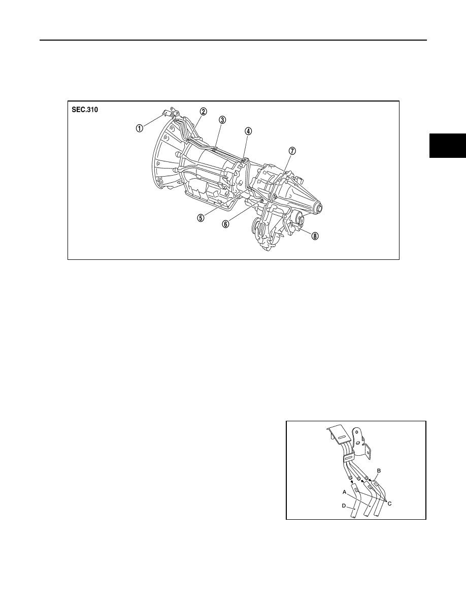
COMPONENTS

REMOVAL

1. Disconnect air breather hose from transfer control device.
2. Disconnect air breather hose from breather tube (transfer).
3. Release air breather hose clamp and clips as necessary.
4. Disconnect air breather hoses from breather tube.

CAUTION:

Note paint marks for installation.

INSTALLATION

CAUTION:

Make sure there are no pinched or restricted areas on each air breather hose caused by folding or

bending when installing it.

1. Install each air breather hose into the breather tube (metal con-

nector) until the hose end reaches the end of the curved section.

Set each air breather hose with paint mark facing upward. 

• A: Transfer control device air breather hose

• B: A/T air breather hose

• C: Paint marks

• D: Transfer air breather hose

1.

Breather tube

2.

Clip A

3.

Clip B

4.

Clip C

5.

Clip D

6.

Breather tube (transfer)

7.

Air breather hose clamp

8.

Transfer control device

SDIA3351E

AWDIA0628GB

August 2012

2012 Pathfinder

DLN-286

< REMOVAL AND INSTALLATION >

[TRANSFER: TX15B]

AIR BREATHER HOSE

2. Install transfer control device air breather hose and transfer air

breather hose on clip A and clip B with the paint mark facing

upward.

3. Install clip C on transfer control device air breather hose and

transfer air breather hose with the paint mark matched.

4. Install transfer control device air breather hose and transfer air

breather hose on clip D with the paint mark facing upward.

5. Install transfer air breather hose into the breather tube (transfer,

metal connector) until the hose end reaches the base of the

tube. Set transfer air breather hose with paint mark facing

upward.

6. Install transfer control device air breather hose into transfer con-

trol device (case connector) until the hose end reaches the base

of the tube. Set transfer control device air breather hose with

paint mark facing forward.

SDIA3353E

SDIA3354E

SDIA3355E

SDIA3196E

SDIA3300E

August 2012

2012 Pathfinder

TRANSFER ASSEMBLY

DLN-287

< UNIT REMOVAL AND INSTALLATION >

[TRANSFER: TX15B]

C

E

F

G

H

I

J

K

L

M

A

B

DLN

N

O

P

UNIT REMOVAL AND INSTALLATION

TRANSFER ASSEMBLY

Removal and Installation

INFOID:0000000007357569

NOTE:

When removing components such as hoses, tubes/lines, etc., cap or plug openings to prevent fluid from spill-

ing.

REMOVAL

1. Switch 4WD shift switch to 2WD and set transfer assembly to 2WD.
2. Remove the under covers using power tool.
3. Partially drain the transfer fluid. Refer to 

DLN-276, "Replacement"

.

4. Remove the center exhaust tube and main muffler. Refer to 

EX-7, "Removal and Installation"

.

5. Remove the front and rear propeller shafts. Refer to 

DLN-319, "Removal and Installation"

 (front), 

DLN-

329, "Removal and Installation"

 (rear).

CAUTION:

Do not damage spline, sleeve yoke and rear oil seal when removing rear propeller shaft.

6. Remove the A/T nuts from the A/T crossmember. Refer to 

TM-198, "4WD : Exploded View"

.

7. Position two suitable jacks under the A/T and transfer assembly.
8. Remove the A/T crossmember. Refer to 

TM-198, "4WD : Exploded View"

.

WARNING:

Support A/T and transfer assembly using two suitable jacks while removing A/T crossmember.

9. Disconnect the electrical connectors from the following:

• ATP switch

• 4LO switch

• Wait detection switch

• Transfer control device

10. Disconnect each air breather hose from the following. Refer to 

TM-189, "4WD : Removal and Installation"

.

• Transfer control device

• Breather tube (transfer)

11. Remove the transfer to A/T and A/T to transfer bolts.
12. Remove the transfer assembly.

WARNING:

Support transfer assembly with suitable jack while removing it.

CAUTION:

Do not damage rear oil seal (A/T).

INSTALLATION

Installation is in the reverse order of removal.

• Tighten the bolts to specification.

• Fill the transfer with new fluid and check for fluid leaks and fluid

level. Refer to 

DLN-276, "Inspection"

.

• Start the engine for one minute. Then stop the engine and recheck

the transfer fluid. Refer to 

DLN-276, "Inspection"

.

• After the installation, check the 4WD shift indicator pattern. If NG,

adjust the position between the transfer assembly and transfer

control unit. Refer to 

DLN-269, "Precaution for Transfer Assembly

and Transfer Control Unit Replacement"

.

Tightening torque

: 36 N·m (3.7kg-m, 27 ft-lb)

SMT872C

August 2012

2012 Pathfinder

DLN-288

< UNIT DISASSEMBLY AND ASSEMBLY >

[TRANSFER: TX15B]

TRANSFER ASSEMBLY

UNIT DISASSEMBLY AND ASSEMBLY

TRANSFER ASSEMBLY

Component Parts Location

INFOID:0000000007357570

1.

Baffle plate

2.

Breather tube

3.

Front case

4.

Snap ring

5.

Input oil seal

6.

Self-lock nut

7.

Companion flange

8.

Front oil seal

9.

4LO switch (gray with green 
paint)

10. ATP switch (black)

11. Rear case

12. Wait detection switch (gray)

13. Gasket

14. Filler plug

15. Drain plug

16. O-ring

17. Transfer control device

18. Harness bracket

19. Dust cover

20. Oil cover

21. Rear oil seal

22. Air breather hose clamp

23. Retainer bolt

24. Gasket

A.

Apply Genuine Anaerobic Liquid 
Gasket or equivalent.

B.

Apply Genuine Silicone RTV or 
equivalent.

AWDIA0749GB

August 2012

2012 Pathfinder

TRANSFER ASSEMBLY

DLN-289

< UNIT DISASSEMBLY AND ASSEMBLY >

[TRANSFER: TX15B]

C

E

F

G

H

I

J

K

L

M

A

B

DLN

N

O

P

Disassembly and Assembly

INFOID:0000000007357571

DISASSEMBLY

1. Remove the drain plug and filler plug.

1.

Input bearing

2.

Snap ring

3.

Internal gear

4.

Carrier bearing

5.

Sun gear

6.

Needle bearing

7.

Metal bushing

8.

Planetary carrier assembly

9.

L-H sleeve

10. Drive chain

11. Mainshaft

12. Sprocket

13. 2-4 sleeve

14. Clutch gear

15. Oil pump assembly

16. Retainer

17. Mainshaft rear bearing

18. Front bearing

19. Front drive shaft

20. Rear bearing

21. L-H shift fork

22. L-H shift rod

23. Retaining pin

24. 2-4 shift bracket

25. 2-4 shift fork

26. Fork guide collar

27. 2-4 shift fork spring

28. Retaining ring

29. Snap ring

30. Shift collar

31. Clevis pin

32. Drum cam

33. Control shift rod

34. Spacer

AWDIA0016GB

August 2012

2012 Pathfinder

DLN-290

< UNIT DISASSEMBLY AND ASSEMBLY >

[TRANSFER: TX15B]

TRANSFER ASSEMBLY

2. Remove the transfer control device from the rear case.
3. Remove the O-ring from the transfer control device.

4. Remove the self-lock nut from the companion flange using suit-

able tool.

5. Put a matching mark on top of the front drive shaft in line with

the mark on the companion flange.

CAUTION:

Use paint to make the matching mark on the front drive

shaft. Do not damage the front drive shaft.

6.  Remove the companion flange using suitable tool.

7. Remove the front oil seal from the front case using Tool.

CAUTION:

Do not damage front case or front drive shaft.

SDIA2212E

SDIA2841E

SDIA2779E

WDIA0133E

Tool number

: ST33290001 (J-34286)

SDIA2423E

August 2012

2012 Pathfinder

TRANSFER ASSEMBLY

DLN-291

< UNIT DISASSEMBLY AND ASSEMBLY >

[TRANSFER: TX15B]

C

E

F

G

H

I

J

K

L

M

A

B

DLN

N

O

P

8. Remove the 4LO switch [gray (with green paint)] and ATP switch

(black) from the front case.

9. Remove the wait detection switch (gray) from the rear case.

10. Remove the dust cover from the rear case using suitable tool.

CAUTION:

Do not damage rear case.

11. Remove oil cover from dust cover.
12. Remove the rear oil seal from the rear case using Tool.

CAUTION:

Do not damage rear case or mainshaft.

PDIA0090E

PDIA0091E

PDIA0092E

Tool number

: ST33290001 (J-34286)

SDIA2424E

August 2012

2012 Pathfinder

DLN-292

< UNIT DISASSEMBLY AND ASSEMBLY >

[TRANSFER: TX15B]

TRANSFER ASSEMBLY

13. Remove the input oil seal from the front case using suitable tool.

CAUTION:

Do not damage front case, sun gear or input bearing.

14. Remove the retainer bolts and gaskets.

CAUTION:

Do not reuse gaskets.

15. Remove the rear case bolts, harness bracket and air breather

hose clamp from the rear case.

16. Separate the front case from the rear case. Then remove the

rear case by prying it up using suitable tool.

CAUTION:

Do not damage the mating surface.

17. Remove the spacer from the control shift rod.

CAUTION:

Do not drop spacer.

18. Remove the snap ring from the mainshaft using suitable tool.

CAUTION:

Do not reuse snap ring.

PDIA0094E

SDIA2789E

SDIA3422E

PDIA0096E

SDIA2430E

August 2012

2012 Pathfinder


Content      ..     213      214      215      216     ..