Nissan Pathfinder (2012 year). Manual - part 201
TRANSFER ASSEMBLY
DLN-173
< UNIT DISASSEMBLY AND ASSEMBLY >
[TRANSFER: ATX14B]
C
E
F
G
H
I
J
K
L
M
A
B
DLN
N
O
P
• Make sure the bearings roll freely and are free from noise, pitting
and cracks.
Main Oil Pump
1. Check the inner and outer circumference, tooth face, and side-
face of the inner and outer gears for damage or abnormal wear.
2. Measure the side clearance between the main oil pump housing
edge and the inner and outer gears.
3. Make sure the side clearance is within specification. If the mea-
surement is out of specification, replace the inner and outer
gears with new ones as a set. Refer to
Sub-oil Pump
1. Check the inner and outer circumference, tooth face, and side-
face of the inner and outer gears for damage or abnormal wear.
2. Measure the side clearance between the sub oil pump housing
edge and the inner and outer gears.
3. Make sure the side clearance is within specification. If the mea-
surement is out of specification, replace the inner and outer
gears with new ones as a set. Refer to
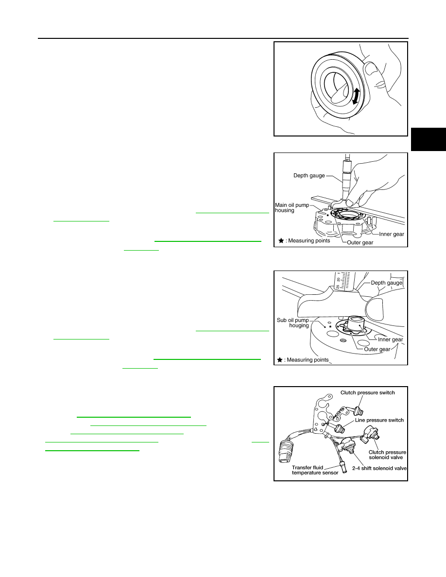
Control Valve
• Check resistance between the terminals of the clutch pressure
solenoid valve, 2-4WD shift solenoid valve, clutch pressure switch,
line pressure switch and the transfer fluid temperature sensor.
Refer to
DLN-63, "Component Inspection"
(clutch pressure sole-
noid valve),
DLN-67, "Component Inspection"
(2-4WD solenoid
valve),
DLN-79, "Component Inspection"
(clutch pressure switch),
DLN-82, "Component Inspection"
(transfer fluid temperature sensor).
SDIA2175E
Specification
Refer to
SDIA2174E
Specification
Refer to
SDIA2173E
WDIA0199E
August 2012
2012 Pathfinder