Nissan Pathfinder (2012 year). Manual - part 179


  Index      Manuals     Nissan Pathfinder (2012 year) - Service and Repair Manual


Search            copyright infringement  


Content      ..     177      178      179      180     ..


Nissan Pathfinder (2012 year). Manual - part 179


FRONT DOOR LOCK

DLK-327

< REMOVAL AND INSTALLATION >

[WITHOUT INTELLIGENT KEY SYSTEM]

C

D

E

F

G

H

I

J

L

M

A

B

DLK

N

O

P

4. Separate the door key cylinder rod from the door key cylinder assembly (if equipped).
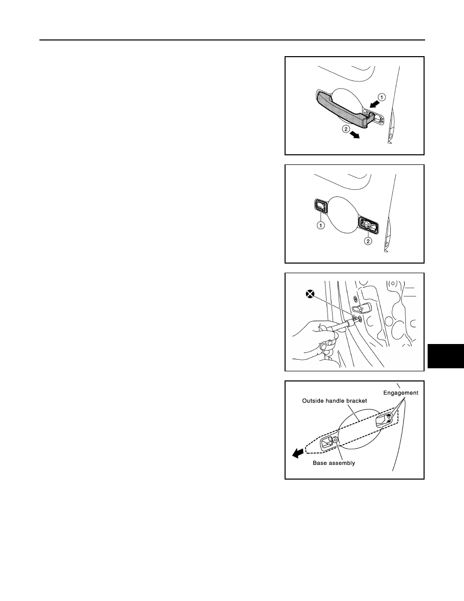
5. While pulling outside handle (1), slide toward rear of vehicle (2)

to remove outside handle.

6. Remove the front gasket (1) and rear gasket (2).

7. Remove the door lock bolts (T30), remove the door lock assem-

bly.

CAUTION:

Do not reuse door lock bolts.

8. While pulling outside handle bracket, slide toward rear of vehicle

to remove outside handle bracket and door lock assembly as

shown.

9. Disconnect the door lock actuator harness connector.

ALKIA0957ZZ

ALKIA0924ZZ

AWKIA2018ZZ

PIIA3558E

August 2012

2012 Pathfinder

2012 Pathfinder

DLK-328

< REMOVAL AND INSTALLATION >

[WITHOUT INTELLIGENT KEY SYSTEM]

FRONT DOOR LOCK

10. Separate the outside handle cable connection from the outside

handle bracket.

INSTALLATION

Installation is in the reverse order of removal.

CAUTION:

• To install the key cylinder rod, be sure to rotate the key cylinder rod holder until a click is felt.

• Do not twist the door lock cable when installing the front door lock. 

Disassembly and Assembly

INFOID:0000000007355658

DOOR KEY CYLINDER ASSEMBLY

Release the key cylinder escutcheon pawls to remove the door key cylinder.

PIIA5059E

1.

Door key cylinder assembly

2.

Door key cylinder escutcheon

3.

Door key cylinder

Pawl

WIIA1057E

August 2012

2012 Pathfinder

2012 Pathfinder

REAR DOOR LOCK

DLK-329

< REMOVAL AND INSTALLATION >

[WITHOUT INTELLIGENT KEY SYSTEM]

C

D

E

F

G

H

I

J

L

M

A

B

DLK

N

O

P

REAR DOOR LOCK

Component Structure

INFOID:0000000007355659

Removal and Installation

INFOID:0000000007355660

REMOVAL

1. Remove the rear door finisher. Refer to 

INT-15, "Removal and Installation"

.

2. Remove the inner seal.
3. Remove door grommets, and remove outside handle nuts from the hole.
4. Remove outside handle.
5. Disconnect the outside handle cable connection.
6. Remove the inside door handle.
7. Disconnect the door lock and inside door handle cables from the inside door handle.
8. Disconnect the door lock actuator connector and remove the assembly.

INSTALLATION

Installation is in the reverse order of removal.

CAUTION:

Do not twist the outside door handle cable, inside door handle cable and door lock cable during instal-

lation. 

1.

Outside door handle

2.

Rear door striker

3.

Rear door lock assembly

4.

Outside door handle cable

5.

Inside door handle cable

6.

Inside door handle assembly

7.

Door lock cable

Vehicle front

AWKIA1794GB

August 2012

2012 Pathfinder

2012 Pathfinder

DLK-330

< REMOVAL AND INSTALLATION >

[WITHOUT INTELLIGENT KEY SYSTEM]

BACK DOOR LOCK

BACK DOOR LOCK

Component Structure

INFOID:0000000007355661

1.

Glass hatch latch assembly

2.

Back door control assembly

3.

Back door striker

4.

Back door latch assembly

5.

Back door release button

6.

Back door finisher

7.

Glass hatch release handle

8.

Glass latch release cable 

9.

Glass hatch release cable

Vehicle front

AWKIA1438GB

August 2012

2012 Pathfinder

2012 Pathfinder

DLN-1

TRANSMISSION & DRIVELINE

C

E

F

G

H

I

J

K

L

M

SECTION 

DLN

A

B

DLN

N

O

P

CONTENTS

DRIVELINE

TRANSFER: ATX14B

BASIC INSPECTION  ....................................

9

DIAGNOSIS AND REPAIR WORKFLOW  ..........

9

Work Flow  .................................................................

9

Preliminary Check  ...................................................

10

SYSTEM DESCRIPTION  .............................

13

4WD SYSTEM  ....................................................

13

System Diagram ......................................................

13

System Description  .................................................

14

Component Parts Location ......................................

19

CAN Communication ...............................................

20

Cross-Sectional View  ..............................................

20

Power Transfer ........................................................

20

DIAGNOSIS SYSTEM (TRANSFER CON-
TROL UNIT) ........................................................

23

CONSULT Function (ALL MODE AWD/4WD)  ........

23

NOISE, VIBRATION AND HARSHNESS 
(NVH) TROUBLESHOOTING  ............................

27

NVH Troubleshooting Chart  ....................................

27

DTC/CIRCUIT DIAGNOSIS  .........................

28

P1811 POWER SUPPLY CIRCUIT FOR 
TRANSFER CONTROL UNIT  ............................

28

Description ..............................................................

28

DTC Logic  ...............................................................

28

Diagnosis Procedure ...............................................

28

Component Inspection  ............................................

29

P1802 – P1804, P1809 TRANSFER CON-
TROL UNIT .........................................................

31

Description ..............................................................

31

DTC Logic  ...............................................................

31

Diagnosis Procedure ...............................................

31

P1807 VEHICLE SPEED SENSOR (A/T)  ..........

33

Description ...............................................................

33

DTC Logic ................................................................

33

Diagnosis Procedure  ...............................................

33

P1808 VEHICLE SPEED SENSOR (ABS)  .......

34

Description ...............................................................

34

DTC Logic ................................................................

34

Diagnosis Procedure  ...............................................

34

P1810 NEUTRAL-4LO SWITCH .......................

35

Description ...............................................................

35

DTC Logic ................................................................

35

Diagnosis Procedure  ...............................................

35

Component Inspection .............................................

37

P1813 4WD SHIFT SWITCH .............................

38

Description ...............................................................

38

DTC Logic ................................................................

38

Diagnosis Procedure  ...............................................

38

Component Inspection .............................................

40

P1814 WAIT DETECTION SWITCH  .................

42

Description ...............................................................

42

DTC Logic ................................................................

42

Diagnosis Procedure  ...............................................

42

Component Inspection .............................................

44

P1816 PNP SWITCH .........................................

45

Description ...............................................................

45

DTC Logic ................................................................

45

Diagnosis Procedure  ...............................................

45

P1817 ACTUATOR MOTOR .............................

46

Description ...............................................................

46

DTC Logic ................................................................

46

Diagnosis Procedure  ...............................................

46

Component Inspection .............................................

50

P1818 ACTUATOR POSITION SWITCH ..........

52

Description ...............................................................

52

DTC Logic ................................................................

52

Diagnosis Procedure  ...............................................

52

August 2012

2012 Pathfinder

DLN-2

Component Inspection ............................................

54

P1819 TRANSFER CONTROL DEVICE  ...........

55

Description ..............................................................

55

DTC Logic ...............................................................

55

Diagnosis Procedure  ..............................................

55

P1820 ENGINE SPEED SIGNAL  ......................

59

Description ..............................................................

59

DTC Logic ...............................................................

59

Diagnosis Procedure  ..............................................

59

P1822 CLUTCH PRESSURE SOLENOID .........

60

Description ..............................................................

60

DTC Logic ...............................................................

60

Diagnosis Procedure  ..............................................

60

Component Inspection ............................................

63

P1823 2-4 SOLENOID  .......................................

64

Description ..............................................................

64

DTC Logic ...............................................................

64

Diagnosis Procedure  ..............................................

64

Component Inspection ............................................

67

P1824 TRANSFER MOTOR  ..............................

68

Description ..............................................................

68

DTC Logic ...............................................................

68

Diagnosis Procedure  ..............................................

68

Component Inspection ............................................

72

P1826 TRANSFER FLUID TEMPERATURE  ....

74

Description ..............................................................

74

DTC Logic ...............................................................

74

Diagnosis Procedure  ..............................................

74

Component Inspection ............................................

75

P1827 CLUTCH PRESSURE SWITCH  .............

77

Description ..............................................................

77

DTC Logic ...............................................................

77

Diagnosis Procedure  ..............................................

77

Component Inspection ............................................

79

P1828 LINE PRESSURE SWITCH ....................

80

Description ..............................................................

80

DTC Logic ...............................................................

80

Diagnosis Procedure  ..............................................

80

Component Inspection ............................................

82

P1829 THROTTLE POSITION SIGNAL (ECM) 

...

83

Description ..............................................................

83

DTC Logic ...............................................................

83

Diagnosis Procedure  ..............................................

83

P1830 ABS OPERATION SIGNAL (ABS)  ........

84

Description ..............................................................

84

DTC Logic ...............................................................

84

Diagnosis Procedure  ..............................................

84

P1831 VDC OPERATION SIGNAL (ABS)  ........

85

Description ..............................................................

85

DTC Logic  ...............................................................

85

Diagnosis Procedure ...............................................

85

P1832 TCS OPERATION SIGNAL (ABS) .........

86

Description ..............................................................

86

DTC Logic  ...............................................................

86

Diagnosis Procedure ...............................................

86

U1010 CONTROL UNIT (CAN)  .........................

87

Description ..............................................................

87

DTC Logic  ...............................................................

87

Diagnosis Procedure ...............................................

87

ECU DIAGNOSIS INFORMATION .............

88

TRANSFER CONTROL UNIT  ...........................

88

Reference Value  .....................................................

88

DTC Index ...............................................................

95

WIRING DIAGRAM  ...................................

100

ALL-MODE 4WD SYSTEM  ..............................

100

Wiring Diagram  .....................................................

100

SYMPTOM DIAGNOSIS  ...........................

110

4WD SYSTEM SYMPTOMS .............................

110

Symptom Table .....................................................

110

4WD SHIFT INDICATOR LAMP AND 4LO IN-
DICATOR LAMP DO NOT TURN ON  ..............

111

Description ............................................................

111

Diagnosis Procedure .............................................

111

4WD WARNING LAMP DOES NOT TURN ON ..

114

Description ............................................................

114

Diagnosis Procedure .............................................

114

4WD SHIFT INDICATOR LAMP OR 4LO INDI-
CATOR LAMP DO NOT CHANGE ...................

117

Description ............................................................

117

Diagnosis Procedure .............................................

117

ATP WARNING LAMP DOES NOT TURN ON ..

119

Description ............................................................

119

Diagnosis Procedure .............................................

119

4WD SHIFT INDICATOR LAMP KEEPS 
FLASHING ........................................................

121

Description ............................................................

121

Diagnosis Procedure .............................................

121

4WD WARNING LAMP FLASHES RAPIDLY ..

122

Description ............................................................

122

Diagnosis Procedure .............................................

122

4WD WARNING LAMP FLASHES SLOWLY ..

123

Description ............................................................

123

Diagnosis Procedure .............................................

123

HEAVY TIGHT-CORNER BRAKING SYMP-
TOM OCCURS ..................................................

124

August 2012

2012 Pathfinder

DLN-3

C

E

F

G

H

I

J

K

L

M

A

B

DLN

N

O

P

Description ............................................................

124

Diagnosis Procedure .............................................

124

ATP SWITCH ....................................................

126

Description ............................................................

126

Diagnosis Procedure .............................................

126

4WD SYSTEM DOES NOT OPERATE  ............

128

Description ............................................................

128

Diagnosis Procedure .............................................

128

PRECAUTION ............................................

129

PRECAUTIONS ................................................

129

Precaution for Supplemental Restraint System 
(SRS) "AIR BAG" and "SEAT BELT PRE-TEN-
SIONER" ...............................................................

129

Precaution Necessary for Steering Wheel Rota-
tion After Battery Disconnect .................................

129

Precaution for Transfer Assembly and Transfer 
Control Unit Replacement  .....................................

130

Precaution .............................................................

130

Service Notice  .......................................................

131

PREPARATION .........................................

132

PREPARATION ................................................

132

Special Service Tool  .............................................

132

Commercial Service Tool  ......................................

134

PERIODIC MAINTENANCE .......................

136

TRANSFER FLUID ...........................................

136

Replacement .........................................................

136

Inspection ..............................................................

136

TRANSFER OIL FILTER ..................................

138

Removal and Installation .......................................

138

REMOVAL AND INSTALLATION .............

140

TRANSFER CONTROL UNIT  ..........................

140

Removal and Installation .......................................

140

FRONT OIL SEAL  ............................................

141

Removal and Installation .......................................

141

REAR OIL SEAL  ..............................................

143

Removal and Installation .......................................

143

SIDE OIL SEAL  ................................................

145

Removal and Installation .......................................

145

TRANSFER CONTROL DEVICE  .....................

146

Removal and Installation .......................................

146

AIR BREATHER HOSE ....................................

147

Removal and Installation .......................................

147

TRANSFER MOTOR  ........................................

152

Removal and Installation .......................................

152

UNIT REMOVAL AND INSTALLATION  ....

153

TRANSFER ASSEMBLY  ................................

153

Removal and Installation  .......................................

153

UNIT DISASSEMBLY AND ASSEMBLY  ..

154

TRANSFER ASSEMBLY  ................................

154

Component Parts Location  ....................................

154

Disassembly and Assembly ...................................

156

SERVICE DATA AND SPECIFICATIONS 
(SDS) ..........................................................

191

SERVICE DATA AND SPECIFICATIONS 
(SDS) ...............................................................

191

General Specification  ............................................

191

Inspection and Adjustment  ....................................

191

TRANSFER: TX15B

BASIC INSPECTION  .................................

193

DIAGNOSIS AND REPAIR WORKFLOW  ......

193

Work Flow ..............................................................

193

SYSTEM DESCRIPTION  ...........................

195

4WD SYSTEM  .................................................

195

System Diagram  ....................................................

195

System Description ................................................

196

Component Parts Location  ....................................

198

CAN Communication  .............................................

199

Cross-Sectional View  ............................................

199

Power Transfer  ......................................................

200

DIAGNOSIS SYSTEM (TRANSFER CON-
TROL UNIT)  ....................................................

202

CONSULT Function (ALL MODE AWD/4WD) .......

202

NOISE, VIBRATION AND HARSHNESS 
(NVH) TROUBLESHOOTING  .........................

205

NVH Troubleshooting Chart  ..................................

205

DTC/CIRCUIT DIAGNOSIS  .......................

206

P1801, P1811 POWER SUPPLY CIRCUIT 
FOR TRANSFER CONTROL UNIT  ................

206

Description .............................................................

206

DTC Logic ..............................................................

206

Diagnosis Procedure  .............................................

206

Component Inspection ...........................................

208

P1802 – P1804, P1809 TRANSFER CON-
TROL UNIT ......................................................

209

Description .............................................................

209

DTC Logic ..............................................................

209

Diagnosis Procedure  .............................................

209

P1807 VEHICLE SPEED SENSOR (A/T)  .......

211

Description .............................................................

211

DTC Logic ..............................................................

211

Diagnosis Procedure  .............................................

211

August 2012

2012 Pathfinder

DLN-4

P1808 VEHICLE SPEED SENSOR (ABS)  ......

212

Description .............................................................

212

DTC Logic ..............................................................

212

Diagnosis Procedure  .............................................

212

P1810 4 LO SWITCH .......................................

213

Description .............................................................

213

DTC Logic ..............................................................

213

Diagnosis Procedure  .............................................

213

Component Inspection ...........................................

215

P1813 4WD SHIFT SWITCH  ...........................

216

Description .............................................................

216

DTC Logic ..............................................................

216

Diagnosis Procedure  .............................................

216

Component Inspection ...........................................

218

P1814 WAIT DETECTION SWITCH ................

219

Description .............................................................

219

DTC Logic ..............................................................

219

Diagnosis Procedure  .............................................

219

Component Inspection ...........................................

221

P1816 PNP SWITCH  .......................................

222

Description .............................................................

222

DTC Logic ..............................................................

222

Diagnosis Procedure  .............................................

222

P1817 ACTUATOR MOTOR  ...........................

223

Description .............................................................

223

DTC Logic ..............................................................

223

Diagnosis Procedure  .............................................

223

Component Inspection ...........................................

228

P1818 ACTUATOR POSITION SWITCH  ........

230

Description .............................................................

230

DTC Logic ..............................................................

230

Diagnosis Procedure  .............................................

230

P1819 TRANSFER CONTROL DEVICE  .........

233

Description .............................................................

233

DTC Logic ..............................................................

233

Diagnosis Procedure  .............................................

233

P1820 ENGINE SPEED SIGNAL  ....................

236

Description .............................................................

236

DTC Logic ..............................................................

236

Diagnosis Procedure  .............................................

236

U1010 CONTROL UNIT (CAN)  .......................

237

Description .............................................................

237

DTC Logic ..............................................................

237

Diagnosis Procedure  .............................................

237

ECU DIAGNOSIS INFORMATION .............

238

TRANSFER CONTROL UNIT ..........................

238

Reference Value ....................................................

238

DTC Index  .............................................................

242

WIRING DIAGRAM  ....................................

245

PART TIME 4WD SYSTEM ..............................

245

Wiring Diagram  .....................................................

245

SYMPTOM DIAGNOSIS  ...........................

254

4WD SYSTEM SYMPTOMS .............................

254

Symptom Table .....................................................

254

4WD WARNING LAMP DOES NOT TURN ON ..

255

Description ............................................................

255

Diagnosis Procedure .............................................

255

4WD SHIFT INDICATOR LAMP AND 4LO IN-
DICATOR LAMP DO NOT TURN ON  ..............

257

Description ............................................................

257

Diagnosis Procedure .............................................

257

4WD SHIFT INDICATOR LAMP OR 4LO INDI-
CATOR LAMP DO NOT CHANGE ...................

259

Description ............................................................

259

Diagnosis Procedure .............................................

259

ATP WARNING LAMP DOES NOT TURN ON ..

261

Description ............................................................

261

Diagnosis Procedure .............................................

261

4WD SHIFT INDICATOR LAMP KEEPS 
FLASHING ........................................................

263

Description ............................................................

263

Diagnosis Procedure .............................................

263

4WD WARNING LAMP FLASHES SLOWLY ..

264

Description ............................................................

264

Diagnosis Procedure .............................................

264

ATP SWITCH ....................................................

265

Description ............................................................

265

Diagnosis Procedure .............................................

265

Component Inspection  ..........................................

267

PRECAUTION ...........................................

268

PRECAUTIONS  ................................................

268

Precaution for Supplemental Restraint System 
(SRS) "AIR BAG" and "SEAT BELT PRE-TEN-
SIONER" ...............................................................

268

Precaution Necessary for Steering Wheel Rota-
tion After Battery Disconnect  ................................

268

Precaution for Transfer Assembly and Transfer 
Control Unit Replacement .....................................

269

Precaution .............................................................

271

Service Notice .......................................................

271

PREPARATION .........................................

273

PREPARATION ................................................

273

Special Service Tool  .............................................

273

Commercial Service Tool ......................................

275

PERIODIC MAINTENANCE ......................

276

TRANSFER FLUID  ...........................................

276

August 2012

2012 Pathfinder


Content      ..     177      178      179      180     ..