Nissan Pathfinder (2012 year). Manual - part 178


  Index      Manuals     Nissan Pathfinder (2012 year) - Service and Repair Manual


Search            copyright infringement  


Content      ..     176      177      178      179     ..


Nissan Pathfinder (2012 year). Manual - part 178


HOOD

DLK-319

< REMOVAL AND INSTALLATION >

[WITHOUT INTELLIGENT KEY SYSTEM]

C

D

E

F

G

H

I

J

L

M

A

B

DLK

N

O

P

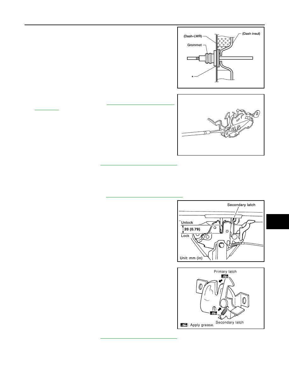
Be careful not to bend the cable too much, keep the radius

100mm (3.94 in) or more.

2. Make sure the cable is not offset from the grommet, and push

the grommet into the lower dash panel hole securely.

3. Apply sealant around the grommet at * mark.

4. Install the cable securely to the lock.
5. Adjust the hood lock. Refer to 

DLK-319, "Hood Lock Control

Inspection"

.

6. Install the front grille. Refer to 

EXT-20, "Removal and Installation"

.

Hood Lock Control Inspection

INFOID:0000000007355652

CAUTION:

If the hood lock cable is bent or deformed, replace it.

1. Remove the front grille. Refer to 

EXT-20, "Removal and Installation"

.

2. Make sure the secondary latch is properly engaged with the sec-

ondary striker with hood's own weight by dropping it from

approx. 200 mm (7.87 in) height.

3. While operating the hood opener, carefully make sure the front

end of the hood is raised by approx. 20 mm (0.79 in). Also make

sure the hood opener returns to the original position.

4. Check the hood lock lubrication condition. If necessary, apply

“body grease” to the points shown.

5. Install the front grille. Refer to 

EXT-20, "Removal and Installation"

.

LIIA1698E

LIIA1699E

PIIA1086E

PIIA0176E

August 2012

2012 Pathfinder

2012 Pathfinder

DLK-320

< REMOVAL AND INSTALLATION >

[WITHOUT INTELLIGENT KEY SYSTEM]

DOOR

DOOR

Fitting Adjustment

INFOID:0000000007355653

FRONT DOOR

Longitudinal clearance and surface height adjustment at front end

1. Remove the fender. Refer to 

EXT-22, "Removal and Installation"

.

2. Loosen the hinge bolts.
3. Raise or lower the front door at rear end to adjust.
4. Tighten the hinge bolts.
5. Install the fender. Refer to 

EXT-22, "Removal and Installation"

.

REAR DOOR

Longitudinal clearance and surface height adjustment at front end

1. Remove the center pillar lower finisher. Refer to 

INT-19, "Removal and Installation"

.

2. Loosen the lower hinge bolts.
3. From inside the vehicle, loosen the upper hinge nuts. Open the door, and raise or lower the rear end of the

door to adjust.

4. Tighten the lower hinge bolts.
5. Install the center pillar lower finisher. Refer to 

INT-19, "Removal and Installation"

.

BACK DOOR

Longitudinal clearance and surface height adjustment 

A.

4.5 

±

 1.0 mm (0.177 

±

 0.039 in)

WIIA0732E

August 2012

2012 Pathfinder

2012 Pathfinder

DOOR

DLK-321

< REMOVAL AND INSTALLATION >

[WITHOUT INTELLIGENT KEY SYSTEM]

C

D

E

F

G

H

I

J

L

M

A

B

DLK

N

O

P

1. Open and support the back door.
2. Slightly loosen the hinge nuts.
3. Reposition the door as necessary and tighten the nuts.
4. Confirm the adjustment. Repeat as necessary to obtain the desired fit.

STRIKER ADJUSTMENT

Body Side Doors

1. Loosen the striker bolts.

1.

Back door assembly

2.

Back door hinge

3.

Rear Combination lamp

4.

Rear bumper fascia

5.

Roof

6.

Side window glass

a.

7.2 

±

 2.0 mm (0.28 

±

 0.08 in)

b.

6.0 

±

 1.5 mm (0.24 

±

 0.06 in)

c.

2.0 

±

 2.0 mm (0.08 

±

 0.08 in)

d.

1.0 

±

 1.5 mm (0.04 

±

 0.06 in)

e.

8.0 

±

 1.5 mm (0.31 

±

 0.06 in)

f.

5.3 

±

 2.0 mm (0.21 

±

 0.08 in)

g.

0.8 

±

 2.0 mm (0.03 

±

 0.08 in)

h.

0.8 

±

 1.0 mm (0.03 

±

 0.04 in)

j.

2.0 

±

 1.0 mm (0.08 

±

 0.04 in)

WIIA0733E

August 2012

2012 Pathfinder

2012 Pathfinder

DLK-322

< REMOVAL AND INSTALLATION >

[WITHOUT INTELLIGENT KEY SYSTEM]

DOOR

2. Adjust the striker so that it becomes parallel with the lock inser-

tion direction.

3. Tighten the striker bolts to specification.

Back Door

1. Loosen the striker bolts.
2. Adjust the striker so that it becomes parallel with the lock inser-

tion direction.

3. Tighten the striker bolts to specification.

Removal and Installation

INFOID:0000000007355654

CAUTION:

• When removing and installing a door assembly, support the door with a jack and shop cloth to pro-

tect the door and body.

• When removing and installing a door assembly, be sure to carry out the fitting adjustment.

• Check the hinge rotating point for poor lubrication. If necessary, apply “body grease”.

FRONT DOOR

Removal

1. Remove the front door glass and regulator. Refer to 

GW-15, "Front Door Glass Regulator"

.

2. Remove the door harness.
3. Remove the check link bolt from the hinge pillar.

AWKIA1766ZZ

WIIA0735E

Check link to hinge pillar 
bolt

14.7 N·m (1.5 kg-m, 11 ft-lb)

LIIA1726E

August 2012

2012 Pathfinder

2012 Pathfinder

DOOR

DLK-323

< REMOVAL AND INSTALLATION >

[WITHOUT INTELLIGENT KEY SYSTEM]

C

D

E

F

G

H

I

J

L

M

A

B

DLK

N

O

P

4. Remove the door-side hinge nuts, and the door assembly.

Installation

Installation is in the reverse order of removal.

Align the front door. Refer to 

DLK-196, "Fitting Adjustment"

.

REAR DOOR

Removal

1. Remove the door finisher. Refer to 

INT-15, "Removal and Installation"

.

2. Remove the inner seal.
3. Remove the rear door speaker. Refer to 

AV-38, "Removal and Installation"

 (BASE AUDIO), 

AV-119,

"Removal and Installation"

 (MID AUDIO), 

AV-260, "Removal and Installation of Rear Door Speaker"

(BOSE AUDIO WITHOUT NAVIGATION) or 

AV-425, "Removal and Installation of Rear Door Speaker"

(BOSE AUDIO WITH NAVIGATION).

4. Remove the rear door tweeter. Refer to 

AV-426, "Removal and Installation of Rear Tweeter"

 (BOSE

AUDIO WITH NAVIGATION).

5. Remove the rear door glass and regulator. Refer to 

GW-19, "Rear Door Glass Regulator"

.

6. Remove the door harness.
7. Remove the check link bolt from the hinge pillar.

8. Remove the door-side hinge nuts, and remove the door assem-

bly.

Installation

Installation is in the reverse order of removal.

Align the rear door. Refer to 

DLK-196, "Fitting Adjustment"

.

BACK DOOR

Removal

Door hinge nuts

24.5 N·m (2.5 kg-m, 18 ft-lb)

LIIA1727E

Check link to hinge pillar 
bolt

14.7 N·m (1.5 kg-m, 11 ft-lb)

LIIA1726E

Door hinge nuts

25.8 N·m (2.6 kg-m, 19 ft-lb)

LIIA1727E

August 2012

2012 Pathfinder

2012 Pathfinder

DLK-324

< REMOVAL AND INSTALLATION >

[WITHOUT INTELLIGENT KEY SYSTEM]

DOOR

1. Remove the glass hatch. Refer to 

GW-24, "Removal and Installation"

.

2. Remove the license lamp finisher. Refer to 

EXT-23, "Removal and Installation"

.

3. Remove the back door lock assembly. Refer to 

DLK-330, "Component Structure"

.

4. Remove the back door wire harness.
5. Remove the rear wiper motor. Refer to 

WW-75, "Removal and Installation"

.

6. Remove the rear washer nozzle and hose from the back door. Refer to 

WW-75, "Removal and Installa-

tion"

7. Remove the high mounted stop light. Refer to 

EXL-151, "High-Mounted Stop Lamp"

.

8. Support the back door.
9. Remove the back door stays.
10. Remove the door side nuts and the back door assembly.

CAUTION:

Two technicians should be used to avoid damaging the back door during removal.

Installation

Installation is in the reverse order of removal.

Align the rear door. Refer to 

DLK-196, "Fitting Adjustment"

.

Back Door Stay Disposal

INFOID:0000000007355655

1. Fix back door stay (1) using a vise (C).
2. Using hacksaw (A) slowly make 2 holes in the back door stay, in

numerical order as shown in the figure.

CAUTION:

• When cutting a hole on back door stay, always cover a

hacksaw using a shop cloth (B) to avoid scattering metal

fragments or oil. 

• Wear eye protection (safety glasses).

• Wear gloves.

WIIA1056E

JMKIA3336ZZ

August 2012

2012 Pathfinder

2012 Pathfinder

DOOR

DLK-325

< REMOVAL AND INSTALLATION >

[WITHOUT INTELLIGENT KEY SYSTEM]

C

D

E

F

G

H

I

J

L

M

A

B

DLK

N

O

P

A: 20 mm (0.787 in)
B: Cut at the groove.

JMKIA3609ZZ

August 2012

2012 Pathfinder

2012 Pathfinder

DLK-326

< REMOVAL AND INSTALLATION >

[WITHOUT INTELLIGENT KEY SYSTEM]

FRONT DOOR LOCK

FRONT DOOR LOCK

Component Structure

INFOID:0000000007355656

Removal and Installation

INFOID:0000000007355657

REMOVAL

1. Remove the front door window regulator. Refer to 

GW-15, "Front Door Glass Regulator"

.

2. Remove door side grommet, and remove door key cylinder

assembly (driver side) or outside handle escutcheon (passenger

side) bolts (1) (T30) from grommet hole.

• (2) Weatherstrip

3. While pulling the outside handle (1), remove door key cylinder

assembly or escutcheon (2).

1.

Grommet

2.

Front door striker

3.

Door lock assembly

4.

Outside handle cable

5.

Inside handle assembly

6.

Inside handle cable

7.

Door lock cable

8.

Key cylinder rod (Driver side only)

9.

Door key cylinder

10. Outside handle bracket

11. Front gasket

12. Outside handle

13. Door key cylinder assembly (Driver 

side) Outside handle escutcheon 
(Passenger side)

14. Rear gasket

Vehicle front

AWKIA1793GB

AWKIA2017ZZ

ALKIA0956ZZ

August 2012

2012 Pathfinder

2012 Pathfinder


Content      ..     176      177      178      179     ..