Nissan Pathfinder (2012 year). Manual - part 170


  Index      Manuals     Nissan Pathfinder (2012 year) - Service and Repair Manual


Search            copyright infringement  


Content      ..     168      169      170      171     ..


Nissan Pathfinder (2012 year). Manual - part 170


KEYFOB BATTERY AND FUNCTION

DLK-255

< DTC/CIRCUIT DIAGNOSIS >

[WITHOUT INTELLIGENT KEY SYSTEM]

C

D

E

F

G

H

I

J

L

M

A

B

DLK

N

O

P

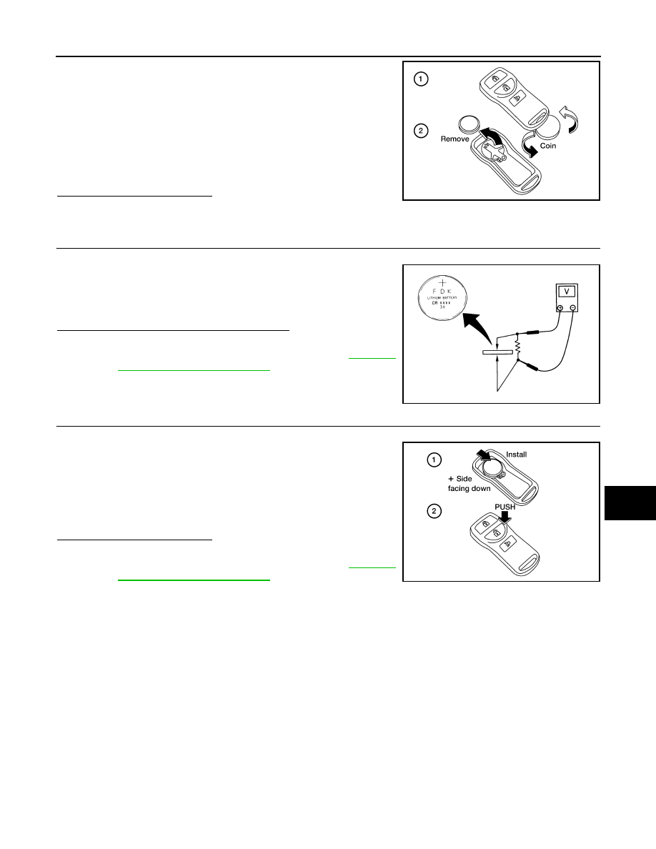
1. Open the lid using a coin.

CAUTION:

• Do not touch the circuit board or battery terminal.

• The keyfob is water-resistant. However, if it does get wet,

immediately wipe it dry. 

2. Remove the key fob battery.

CAUTION:

• Keep dirt, grease, and other foreign materials off the elec-

trode contact area.

3. Visually inspect keyfob internal components.
Is the inspection result normal?

YES

>> GO TO 3

NO

>> Repair or replace malfunctioning parts.

3.

CHECK KEY FOB BATTERY

Check by connecting a resistance (approximately 300

) so that the

current value becomes about 10 mA.

Is the measurement value within specification?

YES

>> Key fob battery is OK. Check remote keyless entry

receiver. Refer to 

DLK-252,

"Component Function Check"

NO

>> GO TO 4

4.

 REPLACE KEY FOB BATTERY

1. Replace the key fob battery, positive side down.

2. Align the tips of the upper and lower parts, and then push them

together until it is securely closed.

CAUTION:

• When replacing battery, keep dirt, grease, and other for-

eign materials off the electrode contact area.

3. After replacing the battery, check that all key fob functions work

properly.

Is the inspection result normal?

YES

>> Key fob is OK.

NO

>> Check remote keyless entry receiver. Refer to 

DLK-252,

"Component Function Check"

.

ALKIA1720GB

Standard

: Approx. 2.5 - 3.0V

OCC0607D

ALKIA1721GB

August 2012

2012 Pathfinder

2012 Pathfinder

DLK-256

< DTC/CIRCUIT DIAGNOSIS >

[WITHOUT INTELLIGENT KEY SYSTEM]

HORN FUNCTION

HORN FUNCTION

Description

INFOID:0000000007355616

Perform answer-back for each operation with horn.

Component Function Check

INFOID:0000000007355617

1.

CHECK FUNCTION

1. Select "HORN" in “ACTIVE TEST” mode with CONSULT.

2. Check the horn (high/low) operation.

Is the operation normal?

YES

>> Inspection End.

NO

>> Refer to 

DLK-256, "Diagnosis Procedure"

.

Diagnosis Procedure

INFOID:0000000007355618

Regarding Wiring Diagram information, refer to 

DLK-292, "Wiring Diagram"

.

1.

CHECK HORN FUNCTION

Check horn function with horn switch.
Does the horn sound?

YES

>> GO TO 2

NO

>> Refer to 

HRN-4, "Wiring Diagram"

.

2.

CHECK HORN RELAY POWER SUPPLY

1. Turn ignition switch ON.

2. Perform “ACTIVE TEST”, "HORN" with CONSULT.

3. Using an oscilloscope or analog voltmeter, check voltage

between IPDM E/R connector E122 terminal 45 and ground.

Is the inspection result normal?

YES

>> Refer to 

GI-37, "Intermittent Incident"

.

NO

>> GO TO 3

3.

CHECK HORN RELAY CIRCUIT

1. Turn ignition switch OFF.

Test item

Description

HORN

ON

Horn relay

ON (for 20 ms)

WIIA1251E

IPDM E/R

Ground

Test item

Voltage (V)

(Approx.)

Connector

Terminal

E122

45

Ground

HORN

OFF 

 ON 

 OFF

Battery voltage 

 0 

 Battery voltage

Other than above

Battery voltage

August 2012

2012 Pathfinder

2012 Pathfinder

HORN FUNCTION

DLK-257

< DTC/CIRCUIT DIAGNOSIS >

[WITHOUT INTELLIGENT KEY SYSTEM]

C

D

E

F

G

H

I

J

L

M

A

B

DLK

N

O

P

2. Disconnect IPDM E/R and horn relay connector.

3. Check continuity between IPDM E/R harness connector and

horn relay harness connector.

4. Check continuity between IPDM E/R harness connector and ground.

Is the inspection result normal?

YES

>> GO TO 4

NO

>> Repair or replace harness.

4.

CHECK INTERMITTENT INCIDENT

Refer to 

GI-37, "Intermittent Incident"

.

Is the inspection result normal?

YES

>> Replace IPDM E/R. Refer to 

PCS-29, "Removal and Installation of IPDM E/R"

.

NO

>> Repair or replace the malfunctioning part.

WIIA1252E

IPDM E/R

Horn relay

Continuity

Connector

Terminal

Connector

Terminal

A: E122

45

B: H-1

1

Yes

IPDM E/R

Ground

Continuity 

Connector

Terminal

E122

45

Ground

No

August 2012

2012 Pathfinder

2012 Pathfinder

DLK-258

< DTC/CIRCUIT DIAGNOSIS >

[WITHOUT INTELLIGENT KEY SYSTEM]

HAZARD FUNCTION

HAZARD FUNCTION

Description

INFOID:0000000007355619

Perform answer-back for each operation with number of blinks.

Component Function Check

INFOID:0000000007355620

1.

CHECK FUNCTION

Check hazard warning lamp "FLASHER" in ACTIVE TEST.
Is the inspection result normal?

YES

>> Hazard warning lamp circuit is OK.

NO

>> Refer to 

DLK-258, "Diagnosis Procedure"

.

Diagnosis Procedure

INFOID:0000000007355621

1.

CHECK HAZARD SWITCH CIRCUIT

Operate the hazard lights by turning ON the hazard warning switch.
Do the lights operate normally?

YES

>> Replace the BCM. Refer to 

BCS-53, "Removal and Installation"

.

NO

>> Repair or replace hazard warning switch circuit. Refer to 

EXL-101, "Wiring Diagram"

.

August 2012

2012 Pathfinder

2012 Pathfinder

KEY SWITCH (BCM INPUT)

DLK-259

< DTC/CIRCUIT DIAGNOSIS >

[WITHOUT INTELLIGENT KEY SYSTEM]

C

D

E

F

G

H

I

J

L

M

A

B

DLK

N

O

P

KEY SWITCH (BCM INPUT)

Diagnosis Procedure

INFOID:0000000007355622

Regarding Wiring Diagram information, refer to 

DLK-280, "Wiring Diagram - Without Intelligent Key System"

.

1.

CHECK KEY SWITCH INPUT SIGNAL

With CONSULT

Check key switch "KEY ON SW" in DATA MONITOR mode with CONSULT. Refer to 

BCS-17, "DOOR LOCK :

CONSULT Function (BCM - DOOR LOCK)"

.

• When key is inserted to ignition key cylinder:

• When key is removed from ignition key cylinder:

Without CONSULT

Check voltage between BCM connector M18 terminal 37 and

ground.

Is the inspection result normal?

YES

>> Key switch (insert) circuit is OK.

NO

>> GO TO 2

2.

CHECK KEY SWITCH (INSERT)

1. Turn ignition switch OFF.

2. Disconnect key switch connector.

3. Check continuity between key switch terminals.

Is the inspection result normal?

YES

>> Repair or replace harness or fuse.

NO

>> Replace key switch.

KEY ON SW

: ON

KEY ON SW

: OFF

Connec-

tor

Terminal

Condition

Voltage (V)

(+)

(–)

M18

37

Ground

Key is inserted.

Battery voltage

Key is removed.

0

LIIA0567E

Terminals

Condition

Continuity

1 – 2

Key is inserted.

Yes

Key is removed.

No

WIIA0559E

August 2012

2012 Pathfinder

2012 Pathfinder

DLK-260

< DTC/CIRCUIT DIAGNOSIS >

[WITHOUT INTELLIGENT KEY SYSTEM]

HEADLAMP FUNCTION

HEADLAMP FUNCTION

Diagnosis Procedure

INFOID:0000000007355623

1.

CHECK HEADLAMP OPERATION

Do headlamps operate with headlamp switch?
YES or NO

YES

>> Headlamp circuit is OK.

NO

>> Check headlamp circuit. Refer to 

EXL-4, "Work Flow"

.

August 2012

2012 Pathfinder

2012 Pathfinder

MAP LAMP AND IGNITION KEYHOLE ILLUMINATION FUNCTION

DLK-261

< DTC/CIRCUIT DIAGNOSIS >

[WITHOUT INTELLIGENT KEY SYSTEM]

C

D

E

F

G

H

I

J

L

M

A

B

DLK

N

O

P

MAP LAMP AND IGNITION KEYHOLE ILLUMINATION FUNCTION

Diagnosis Procedure

INFOID:0000000007355624

1.

CHECK MAP LAMP OPERATION

When room lamp switch is in "DOOR" position, open the driver or passenger door.

Map lamp and ignition keyhole illumination should illuminate.
Is the inspection result normal?

YES

>> Map lamp circuit is OK.

NO

>> Check map lamp circuit. Refer to 

INL-3, "Work Flow"

.

August 2012

2012 Pathfinder

2012 Pathfinder

DLK-262

< DTC/CIRCUIT DIAGNOSIS >

[WITHOUT INTELLIGENT KEY SYSTEM]

KEYFOB ID SET UP WITH CONSULT

KEYFOB ID SET UP WITH CONSULT

ID Code Entry Procedure

INFOID:0000000007355625

KEYFOB ID SET UP WITH CONSULT

NOTE:

If a keyfob is lost, the ID code of the lost keyfob must be erased to prevent unauthorized use. A spe-

cific ID code can be erased with CONSULT. However, when the ID code of a lost keyfob is not known,

all controller ID codes should be erased. After all ID codes are erased, the ID codes of all remaining

and/or new keyfobs must be re-registered.

When registering an additional keyfob, the existing ID codes in memory may or may not be erased. If

five ID codes are stored in memory when an additional code is registered, only the oldest code is

erased. If less than five codes are stored in memory when an additional code is registered, the new

ID code is added and no ID codes are erased.

Entry of a maximum of five ID codes is allowed. When more than five codes are entered, the oldest ID

code will be erased.

Even if the same ID code that is already in memory is input, the same ID code can be entered. The

code is counted as an additional code.

1. Turn ignition switch ON.
2. Select “BCM”.
3. Select “MULTI REMOTE ENT”.
4. Select “WORK SUPPORT”.
5. You can register, erase or confirm a keyfob ID code. To register a new code, select the following option

and follow CONSULT instructions:

• “REMO CONT ID REGIST”

Use this mode to register a keyfob ID code.

NOTE:

Register the ID code when keyfob or BCM is replaced, or when additional keyfob is required.

• “REMO CONT ID ERASUR”

Use this mode to erase a keyfob ID code.

• “REMO CONT ID CONFIR”

Use this mode to confirm if a keyfob ID code is registered or not.

August 2012

2012 Pathfinder

2012 Pathfinder


Content      ..     168      169      170      171     ..