Nissan Pathfinder (2012 year). Manual - part 168


  Index      Manuals     Nissan Pathfinder (2012 year) - Service and Repair Manual


Search            copyright infringement  


Content      ..     166      167      168      169     ..


Nissan Pathfinder (2012 year). Manual - part 168


BACK DOOR OPENER SWITCH

DLK-239

< DTC/CIRCUIT DIAGNOSIS >

[WITHOUT INTELLIGENT KEY SYSTEM]

C

D

E

F

G

H

I

J

L

M

A

B

DLK

N

O

P

BACK DOOR OPENER SWITCH

Diagnosis Procedure

INFOID:0000000007355589

Regarding Wiring Diagram information, refer to 

DLK-280, "Wiring Diagram - Without Intelligent Key System"

.

1.

CHECK BACK DOOR OPENER SWITCH

With CONSULT

Check back door opener switch (“TRNK OPNR SW”) in “DATA MONITOR” mode.
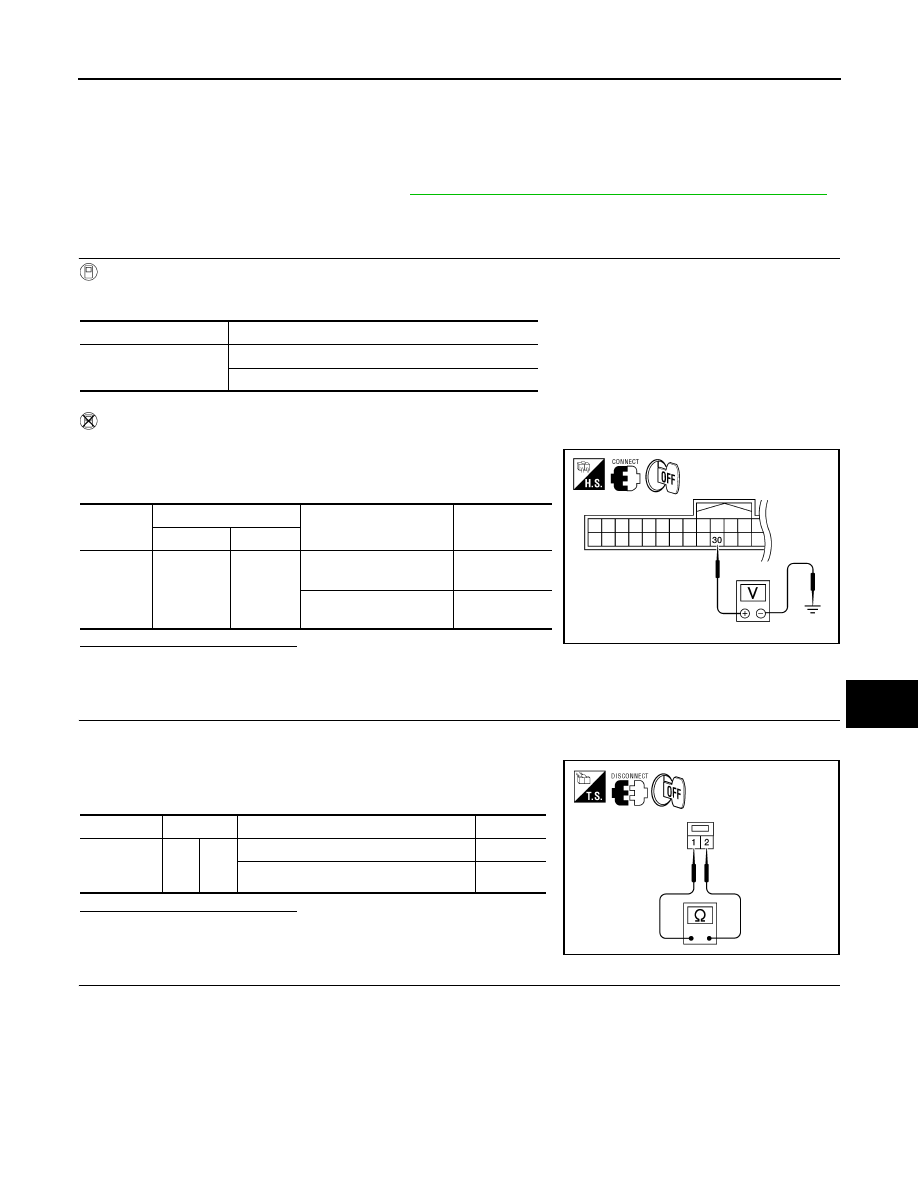
Without CONSULT

1. Turn ignition switch OFF.

2. Check voltage between BCM connector M18 terminal 30 and

ground.

Is the inspection result normal?

YES

>> Back door opener switch is OK.

NO

>> GO TO 2

2.

CHECK BACK DOOR OPENER SWITCH OPERATION

1. Turn ignition switch OFF.

2. Disconnect back door opener switch connector.

3. Check continuity between back door opener switch terminals 1

and 2.

Is the inspection result normal?

YES

>> GO TO 3

NO

>> Replace back door opener switch.

3.

CHECK BACK DOOR OPENER SWITCH GROUND CIRCUIT

NOTE:

The passenger door must be unlocked during this step.

Check continuity between back door opener switch harness connector D510 terminal 2 and ground.

Monitor item

Condition

TRNK OPNR SW

Back door opener switch is pressed: ON

Back door opener switch is released: OFF

Connector

Terminals

Condition

Voltage (V)

(Approx.)

(+)

(–)

M18

30

Ground

Back door opener switch 

is pressed

0

Back door opener switch 

is released

5

ALKIA1713ZZ

Component

Terminals

Condition

Continuity

Back door 

opener 

switch

1

2

Back door opener switch is pressed

Yes

Back door opener switch is released

No

WIIA1186E

August 2012

2012 Pathfinder

2012 Pathfinder

DLK-240

< DTC/CIRCUIT DIAGNOSIS >

[WITHOUT INTELLIGENT KEY SYSTEM]

BACK DOOR OPENER SWITCH

Is the inspection result normal?

YES

>> GO TO 4

NO

>> GO TO 5

4.

CHECK BACK DOOR OPENER SWITCH CIRCUIT

1. Disconnect BCM.

2. Check continuity between BCM harness connector (A) M18 ter-

minal 30 and back door opener switch harness connector (B)

D510 terminal 1.

3. Check continuity between BCM harness connector (A) M18 ter-

minal 30 and ground.

Is the inspection result normal?

YES

>> Replace BCM. Refer to 

BCS-53, "Removal and Installa-

tion"

.

NO

>> Repair or replace harness between BCM and back door opener switch.

5.

CHECK BACK DOOR OPENER SWITCH GROUND CIRCUIT

1. Disconnect front door lock assembly RH (door unlock sensor).

2. Check continuity between back door opener switch harness

connector (A) D510 terminal 2 and front door lock assembly RH

(door unlock sensor) connector (B) D103 terminal 3.

3. Check continuity between back door opener switch harness

connector (A) D510 terminal 2 and ground.

Is the inspection result normal?

YES

>> GO TO 6

NO

>> Repair or replace harness.

6.

CHECK DOOR UNLOCK SENSOR CIRCUIT

1. Check continuity between front door lock assembly RH (door

unlock sensor) connector D103 terminal 5 and ground.

Is the inspection result normal?

YES

>> Replace front door lock assembly RH (door unlock sen-

sor).

NO

>> Repair or replace harness for open.

2 - Ground

: Continuity should exist.

WIIA1187E

30 - 1

: Continuity should exist.

30 - Ground

: Continuity should not exist.

ALKIA1714ZZ

2 - 3

: Continuity should exist.

2 - Ground

: Continuity should not exist.

ALKIA1715ZZ

5 - Ground

: Continuity should exist.

ALKIA1734ZZ

August 2012

2012 Pathfinder

2012 Pathfinder

KEY CYLINDER SWITCH

DLK-241

< DTC/CIRCUIT DIAGNOSIS >

[WITHOUT INTELLIGENT KEY SYSTEM]

C

D

E

F

G

H

I

J

L

M

A

B

DLK

N

O

P

KEY CYLINDER SWITCH

Description

INFOID:0000000007355590

The main power window and door lock/unlock switch detects condition of the door key cylinder switch and

transmits to BCM as the LOCK or UNLOCK signal. 

Component Function Check

INFOID:0000000007355591

1.

CHECK DOOR KEY CYLINDER SWITCH INPUT SIGNAL

Check "KEY CYL LK-SW" AND "KEY CYL UN-SW" in DATA MONITOR mode for “POWER DOOR LOCK

SYSTEM” with CONSULT.

Is the inspection result normal?

YES

>> Key cylinder switch is OK.

NO

>> Refer to 

DLK-241, "Diagnosis Procedure"

.

Diagnosis Procedure

INFOID:0000000007355592

Regarding Wiring Diagram information, refer to 

DLK-280, "Wiring Diagram - Without Intelligent Key System"

.

1.

CHECK DOOR KEY CYLINDER SWITCH LH

With CONSULT

Check front door lock assembly LH (key cylinder switch) ("KEY CYL LK-SW") and ("KEY CYL UN-SW) in

DATA MONITOR mode with CONSULT.

• When key inserted in left front key cylinder is turned to LOCK:

• When key inserted in left front key cylinder is turned to UNLOCK:

Without CONSULT

Check voltage between main power window and door lock/unlock

switch connector D7 terminals 4, 6 and ground.

Is the inspection result normal?

YES

>> Key cylinder switch signal is OK.

Monitor item

Condition

KEY CYL LK-SW

Lock

: ON

Neutral / Unlock

: OFF

KEY CYL UN-SW

Unlock

: ON

Neutral / Lock

: OFF

KEY CYL LK-SW

: ON

KEY CYL UN-SW

: ON

Connector

Terminals

Condition of left front key cylinder

Voltage (V)

(Approx.)

(+)

(–)

D7

4

Ground

Neutral/Unlock

5

Lock

0

6

Neutral/Lock

5

Unlock

0

LIIA0566E

August 2012

2012 Pathfinder

2012 Pathfinder

DLK-242

< DTC/CIRCUIT DIAGNOSIS >

[WITHOUT INTELLIGENT KEY SYSTEM]

KEY CYLINDER SWITCH

NO

>> GO TO 2

2.

CHECK DOOR KEY CYLINDER SWITCH LH GROUND HARNESS

1. Turn ignition switch OFF.

2. Disconnect front door lock assembly LH (key cylinder switch).

3. Check continuity between front door lock assembly LH (key cyl-

inder switch) connector (A) D14 terminal 4 and body ground.

Is the inspection result normal?

YES

>> GO TO 3

NO

>> Repair or replace harness.

3.

CHECK DOOR KEY CYLINDER SWITCH LH

Check continuity between front door lock assembly LH (key cylinder

switch) terminals.

Is the inspection result normal?

YES

>> GO TO 4

NO

>> Replace front door lock assembly LH (key cylinder switch). Refer to 

DLK-326, "Removal and

Installation"

.

4.

CHECK DOOR KEY CYLINDER HARNESS

Check continuity between main power window and door lock/unlock

switch connector (A) D7 terminals 4, 6 and front door lock assembly

LH (key cylinder switch) connector (B) D14 terminals 3, 5 and body

ground. 

Is the inspection result normal?

YES

>> Replace main power window and door lock/unlock switch.

NO

>> Repair or replace harness.

Connector

Terminals

Continuity

D14

4 – Ground

Yes

ALKIA1186ZZ

Terminals

Condition

Continuity

3 – 4

Key is turned to LOCK or neutral.

No

Key is turned to UNLOCK.

Yes

4 – 5

Key is turned to UNLOCK or neutral.

No

Key is turned to LOCK.

Yes

ALKIA1183ZZ

Connector

Terminals

Connector

Terminals

Continuity

A: Main 

power win-

dow and 

door lock/

unlock 

switch

4

B:  Front 

door lock 

assembly 

LH (key 
cylinder 

switch)

5

Yes

6

3

Yes

4, 6

Ground

No

ALKIA1184ZZ

August 2012

2012 Pathfinder

2012 Pathfinder

DOOR LOCK ACTUATOR

DLK-243

< DTC/CIRCUIT DIAGNOSIS >

[WITHOUT INTELLIGENT KEY SYSTEM]

C

D

E

F

G

H

I

J

L

M

A

B

DLK

N

O

P

DOOR LOCK ACTUATOR

DRIVER SIDE
DRIVER SIDE : Description

INFOID:0000000007355593

Locks/unlocks the door with the signal from BCM.

DRIVER SIDE : Component Function Check

INFOID:0000000007355594

1.

CHECK FUNCTION

1. Use CONSULT to perform Active Test "DOOR LOCK".

2. Touch “ALL LOCK” or “ALL UNLOCK” to check that it works normally.
Is the inspection result normal?

YES

>> Door lock actuator is OK.

NO

>> Refer to 

DLK-243, "DRIVER SIDE : Diagnosis Procedure"

.

DRIVER SIDE : Diagnosis Procedure

INFOID:0000000007355595

Regarding Wiring Diagram information, refer to 

DLK-280, "Wiring Diagram - Without Intelligent Key System"

.

1.

CHECK DOOR LOCK ACTUATOR SIGNAL

1. Turn ignition switch OFF.

2. Check voltage between BCM connector M20 terminals 59, 65

and ground.

Is the inspection result normal?

YES

>> GO TO 2

NO

>> GO TO 3

2.

CHECK DOOR LOCK ACTUATOR HARNESS

1. Disconnect BCM and front door lock assembly LH (actuator).

2. Check continuity between BCM connector (A) M20 terminals 59,

65 and front door lock assembly LH (actuator) connector (B)

D14 terminals 1, 2. 

Is the inspection result normal?

YES

>> Replace front door lock assembly LH (actuator).

NO

>> Repair or replace harness.

Connector

Terminals

Condition

Voltage (V)

(Approx.)

(+)

(-)

M20

59

Ground

Driver door lock/unlock 
switch is turned to UN-
LOCK

 Battery voltage

65

Driver door lock/unlock 
switch is turned to LOCK

 Battery voltage

LIIA1046E

Connector

Terminals

Connector

Terminals

Continuity

M20

59

D14

2

Yes

65

1

ALKIA1191ZZ

August 2012

2012 Pathfinder

2012 Pathfinder

DLK-244

< DTC/CIRCUIT DIAGNOSIS >

[WITHOUT INTELLIGENT KEY SYSTEM]

DOOR LOCK ACTUATOR

3.

CHECK DOOR LOCK ACTUATOR HARNESS

1. Disconnect BCM and front door lock assembly LH (actuator).

2. Check continuity between BCM connector M20 terminals 59, 65

and ground.

Is the inspection result normal?

YES

>> Replace BCM. Refer to 

BCS-53, "Removal and Installation"

.

NO

>> Repair or replace harness.

PASSENGER SIDE
PASSENGER SIDE : Description

INFOID:0000000007355596

Locks/unlocks the door with the signal from BCM.

PASSENGER SIDE : Component Function Check

INFOID:0000000007355597

1.

CHECK FUNCTION

1. Use CONSULT to perform Active Test DOOR LOCK.

2. Touch “ALL LOCK” or “ALL UNLOCK” to check that it works normally.
Is the inspection result normal?

YES

>> Door lock actuator is OK.

NO

>> Refer to 

DLK-244, "PASSENGER SIDE : Diagnosis Procedure"

.

PASSENGER SIDE : Diagnosis Procedure

INFOID:0000000007355598

Regarding Wiring Diagram information, refer to 

DLK-280, "Wiring Diagram - Without Intelligent Key System"

.

1.

CHECK DOOR LOCK ACTUATOR SIGNAL

1. Turn ignition switch OFF.

2. Check voltage between BCM connector M20 terminals 65, 66

and ground.

Is the inspection result normal?

YES

>> GO TO 2

NO

>> GO TO 3

Connector

Terminals

Continuity

M20

59

Ground

No

65

ALKIA0633ZZ

Connector

Terminals

Condition

Voltage (V)

(Approx.)

(+)

(-)

M20

65

Ground

Door lock/unlock switch is 
turned to LOCK

 Battery voltage 

for 300 ms

66

Door lock/unlock switch is 
turned to UNLOCK

LIIA1048E

August 2012

2012 Pathfinder

2012 Pathfinder

DOOR LOCK ACTUATOR

DLK-245

< DTC/CIRCUIT DIAGNOSIS >

[WITHOUT INTELLIGENT KEY SYSTEM]

C

D

E

F

G

H

I

J

L

M

A

B

DLK

N

O

P

2.

CHECK DOOR LOCK ACTUATOR HARNESS

1. Disconnect BCM and front door lock assembly RH (door lock actuator).

2. Check continuity between BCM connector (A) M20 terminals 65,

66 and front door lock assembly RH (door lock actuator) (B)

D119 terminals 1, 2.

Is the inspection result normal?

YES

>> Replace front door lock assembly RH (door lock actuator). Refer to 

DLK-326, "Removal and

Installation"

.

NO

>> Repair or replace harness.

3.

CHECK DOOR LOCK ACTUATOR HARNESS

1. Disconnect BCM and front door lock assembly RH (door lock actuator).

2. Check continuity between BCM connector M19 terminals 65, 66

and ground.

Is the inspection result normal?

YES

>> Replace BCM. Refer to 

BCS-53, "Removal and Installation"

.

NO

>> Repair or replace harness.

REAR LH
REAR LH : Description

INFOID:0000000007355599

Locks/unlocks the door with the signal from BCM.

REAR LH : Component Function Check

INFOID:0000000007355600

1.

CHECK FUNCTION

1. Use CONSULT to perform Active Test "DOOR LOCK".

2. Touch “ALL LOCK” or “ALL UNLOCK” to check that it works normally.
Is the inspection result normal?

YES

>> Door lock actuator is OK.

NO

>> Refer to 

DLK-245, "REAR LH : Diagnosis Procedure"

.

REAR LH : Diagnosis Procedure

INFOID:0000000007355601

Regarding Wiring Diagram information, refer to 

DLK-280, "Wiring Diagram - Without Intelligent Key System"

.

Terminal

Continuity

65

2

Yes

66

1

ALKIA1192ZZ

Terminals

Continuity

65

Ground

No

66

ALKIA0631ZZ

August 2012

2012 Pathfinder

2012 Pathfinder

DLK-246

< DTC/CIRCUIT DIAGNOSIS >

[WITHOUT INTELLIGENT KEY SYSTEM]

DOOR LOCK ACTUATOR

1.

CHECK DOOR LOCK ACTUATOR SIGNAL

1. Turn ignition switch OFF.

2. Check voltage between BCM connector M20 terminals 65, 66

and ground.

Is the inspection result normal?

YES

>> GO TO 2

NO

>> GO TO 3

2.

CHECK DOOR LOCK ACTUATOR HARNESS

NOTE:

The passenger select unlock relay must remain connected during this test. 

1. Disconnect BCM and rear door lock actuator LH.

2. Check continuity between BCM connector (A) M20 terminals 65,

66 and rear door lock actuator LH connector (B) D205 terminals

1, 2.

Is the inspection result normal?

YES

>> Replace rear door lock actuator LH.

NO

>> Repair or replace harness or passenger select unlock relay.

3.

CHECK DOOR LOCK ACTUATOR HARNESS

1. Disconnect BCM and each door lock actuator.

2. Check continuity between BCM connector M20 terminals 65, 66

and ground.

Is the inspection result normal?

YES

>> Replace BCM. Refer to 

BCS-53, "Removal and Installation"

.

NO

>> Repair or replace harness or passenger select unlock relay.

REAR RH

Connector

Terminals

Condition

Voltage (V)

(Approx.)

(+)

(-)

M20

65

Ground

Door lock/unlock switch 
is turned to LOCK

 Battery voltage 

for 300 ms

66

Door lock/unlock switch 
is turned to UNLOCK

LIIA1048E

Terminals

Continuity

65

2

Yes

66

1

ALKIA1192ZZ

Terminals

Continuity

65

Ground

No

66

No

ALKIA0631ZZ

August 2012

2012 Pathfinder

2012 Pathfinder


Content      ..     166      167      168      169     ..