Nissan Pathfinder (2012 year). Manual - part 116


  Index      Manuals     Nissan Pathfinder (2012 year) - Service and Repair Manual


Search            copyright infringement  


Content      ..     114      115      116      117     ..


Nissan Pathfinder (2012 year). Manual - part 116


BRC-194

< DTC/CIRCUIT DIAGNOSIS >

[TYPE 2]

VDC OFF SWITCH

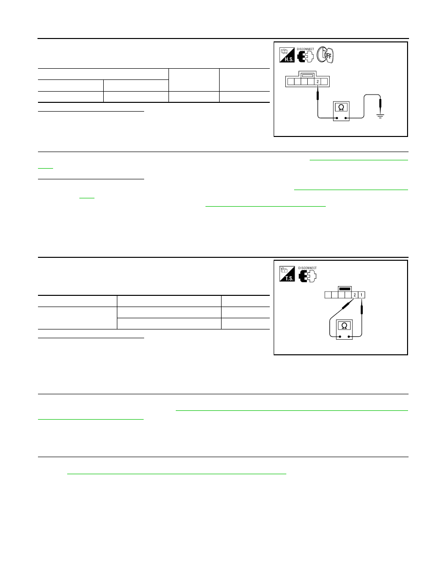
Check continuity between VDC OFF switch connector M154 and

ground.

Is the inspection result normal?

YES

>> GO TO 4

NO

>> Repair or replace harness.

4.

CHECK COMBINATION METER

Check if the indication and operation of combination meter are normal. Refer to 

MWI-25, "Diagnosis Descrip-

tion"

.

Is the inspection result normal?

YES

>> Replace ABS actuator and electric unit (control unit). Refer to 

BRC-231, "Removal and Installa-

tion"

.

NO

>> Replace combination meter. Refer to 

MWI-89, "Removal and Installation"

.

Component Inspection

INFOID:0000000007356945

INSPECTION PROCEDURE

1.

CHECK VDC OFF SWITCH

1. Turn ignition switch OFF.

2. Disconnect VDC OFF switch connector.

3. Check continuity between VDC OFF switch terminals.

Is the inspection result normal?

YES

>> Inspection End.

NO

>> Replace VDC OFF switch.

Special Repair Requirement

INFOID:0000000007818508

1.

ADJUSTMENT OF STEERING ANGLE SENSOR NEUTRAL POSITION

Always perform neutral position adjustment for the steering angle sensor when replacing the ABS actuator

and electric unit (control unit). Refer to 

BRC-121, "ADJUSTMENT OF STEERING ANGLE SENSOR NEU-

TRAL POSITION : Description"

.

>> GO TO 2

2.

CALIBRATION OF DECEL G SENSOR

Always perform calibration of decel G sensor when replacing the ABS actuator and electric unit (control unit).

Refer to 

BRC-122, "CALIBRATION OF DECEL G SENSOR : Description"

.

>> END

VDC OFF switch

Continuity

Connector

Terminal

M154

2

Ground

Yes

AWFIA0031ZZ

VDC OFF switch terminals

Condition

Continuity

 2

When VDC OFF switch is pressed.

Yes

When VDC OFF switch is released.

No

AWFIA0446ZZ

August 2012

2012 Pathfinder

ABS WARNING LAMP

BRC-195

< DTC/CIRCUIT DIAGNOSIS >

[TYPE 2]

C

D

E

G

H

I

J

K

L

M

A

B

BRC

N

O

P

ABS WARNING LAMP

Description

INFOID:0000000007356947

×

: ON –: OFF

Component Function Check

INFOID:0000000007356948

1.

CHECK ABS WARNING LAMP OPERATION

Check that the lamp illuminates for approximately 2 seconds after the ignition switch is turned ON.
Is the inspection result normal?

YES

>> Inspection End.

NO

>> Go to diagnosis procedure. Refer to 

BRC-195, "Diagnosis Procedure"

.

Diagnosis Procedure

INFOID:0000000007356949

1.

CHECK SELF-DIAGNOSIS

Perform ABS actuator and electric unit (control unit) self-diagnosis. Refer to 

BRC-138, "CONSULT Function

(ABS)"

.

Is the inspection result normal?

YES

>> GO TO 2

NO

>> Check items displayed by self-diagnosis.

2.

CHECK COMBINATION METER

Check if the indication and operation of combination meter are normal. Refer to 

MWI-25, "Diagnosis Descrip-

tion"

.

Is the inspection result normal?

YES

>> Replace ABS actuator and electric unit (control unit). Refer to 

BRC-231, "Removal and Installa-

tion"

.

NO

>> Replace combination meter. Refer to 

MWI-89, "Removal and Installation"

.

Special Repair Requirement

INFOID:0000000007818509

1.

ADJUSTMENT OF STEERING ANGLE SENSOR NEUTRAL POSITION

Always perform neutral position adjustment for the steering angle sensor when replacing the ABS actuator

and electric unit (control unit). Refer to 

BRC-121, "ADJUSTMENT OF STEERING ANGLE SENSOR NEU-

TRAL POSITION : Description"

.

>> GO TO 2

2.

CALIBRATION OF DECEL G SENSOR

Always perform calibration of decel G sensor when replacing the ABS actuator and electric unit (control unit).

Refer to 

BRC-122, "CALIBRATION OF DECEL G SENSOR : Description"

.

>> END

Condition

ABS warning lamp

Ignition switch OFF

For 2 seconds after turning ON ignition switch

×

2 seconds later after turning ON ignition switch

ABS function is malfunctioning.

×

EBD function is malfunctioning.

×

August 2012

2012 Pathfinder

BRC-196

< DTC/CIRCUIT DIAGNOSIS >

[TYPE 2]

BRAKE WARNING LAMP

BRAKE WARNING LAMP

Description

INFOID:0000000007356951

×

: ON –: OFF

NOTE:

• 1: Brake warning lamp will turn on in case of parking brake operation (when switch is ON) or of brake fluid level switch operation

(when brake fluid is insufficient).

• 2: After starting engine, brake warning lamp is turned off.

Component Function Check

INFOID:0000000007356952

1.

BRAKE WARNING LAMP OPERATION CHECK

Check that the lamp illuminates after the ignition switch is turned ON, and turns OFF after the engine is

started.
Is the inspection result normal?

YES

>> Inspection End.

NO

>> Go to diagnosis procedure. Refer to 

BRC-196, "Diagnosis Procedure"

.

Diagnosis Procedure

INFOID:0000000007356953

1.

CHECK SELF-DIAGNOSIS

Perform ABS actuator and electric unit (control unit) self-diagnosis. Refer to 

BRC-138, "CONSULT Function

(ABS)"

.

Is the inspection result normal?

YES

>> GO TO 2

NO

>> Check items displayed by self-diagnosis.

2.

CHECK COMBINATION METER

Check if the indication and operation of combination meter are normal. Refer to 

MWI-25, "Diagnosis Descrip-

tion"

.

Is the inspection result normal?

YES

>> Replace ABS actuator and electric unit (control unit). Refer to 

BRC-231, "Removal and Installa-

tion"

.

NO

>> Replace combination meter. Refer to 

MWI-89, "Removal and Installation"

.

Special Repair Requirement

INFOID:0000000007818512

1.

ADJUSTMENT OF STEERING ANGLE SENSOR NEUTRAL POSITION

Always perform neutral position adjustment for the steering angle sensor when replacing the ABS actuator

and electric unit (control unit). Refer to 

BRC-121, "ADJUSTMENT OF STEERING ANGLE SENSOR NEU-

TRAL POSITION : Description"

.

>> GO TO 2

2.

CALIBRATION OF DECEL G SENSOR

Always perform calibration of decel G sensor when replacing the ABS actuator and electric unit (control unit).

Refer to 

BRC-122, "CALIBRATION OF DECEL G SENSOR : Description"

.

>> END

Condition

Brake warning lamp (Note 1)

Ignition switch OFF

Ignition switch ON

×

 (Note 2)

EBD function is malfunctioning.

×

August 2012

2012 Pathfinder

VDC OFF INDICATOR LAMP

BRC-197

< DTC/CIRCUIT DIAGNOSIS >

[TYPE 2]

C

D

E

G

H

I

J

K

L

M

A

B

BRC

N

O

P

VDC OFF INDICATOR LAMP

Description

INFOID:0000000007356955

×

: ON –: OFF

Component Function Check

INFOID:0000000007356956

1.

VDC OFF INDICATOR LAMP OPERATION CHECK 1

Check that the lamp illuminates for approximately 2 seconds after the ignition switch is turned ON.
Is the inspection result normal?

YES

>> GO TO 2

NO

>> Go to diagnosis procedure. Refer to 

BRC-197, "Diagnosis Procedure"

.

2.

VDC OFF INDICATOR LAMP OPERATION CHECK 2

Check that the VDC OFF indicator lamp in the combination meter turns ON/OFF correctly when operating the

VDC OFF switch.
Is the inspection result normal?

YES

>> Inspection End.

NO

>> Check VDC OFF switch. Refer to 

BRC-193, "Diagnosis Procedure"

.

Diagnosis Procedure

INFOID:0000000007356957

1.

CHECK VDC OFF SWITCH

Check that the VDC OFF indicator lamp in the combination meter turns ON/OFF correctly when operating the

VDC OFF switch.
Is the inspection result normal?

YES

>> GO TO 2

NO

>> Check VDC OFF switch. Refer to 

BRC-193, "Diagnosis Procedure"

.

2.

CHECK SELF-DIAGNOSIS

Perform ABS actuator and electric unit (control unit) self-diagnosis. Refer to 

BRC-138, "CONSULT Function

(ABS)"

.

Is the inspection result normal?

YES

>> GO TO 3

NO

>> Check items displayed by self-diagnosis.

3.

CHECK COMBINATION METER

Check if the indication and operation of combination meter are normal. Refer to 

MWI-25, "Diagnosis Descrip-

tion"

.

Is the inspection result normal?

YES

>> Replace ABS actuator and electric unit (control unit). Refer to 

BRC-231, "Removal and Installa-

tion"

.

NO

>> Replace combination meter. Refer to 

MWI-89, "Removal and Installation"

.

Condition

VDC OFF indicator lamp

Ignition switch OFF

For 2 seconds after turning ON ignition switch

×

2 seconds later after turning ON ignition switch

VDC OFF switch turned ON. (VDC function is OFF.)

×

VDC/TCS function is malfunctioning.

ABS function is malfunctioning.

EBD function is malfunctioning.

August 2012

2012 Pathfinder

BRC-198

< DTC/CIRCUIT DIAGNOSIS >

[TYPE 2]

VDC OFF INDICATOR LAMP

Special Repair Requirement

INFOID:0000000007818510

1.

ADJUSTMENT OF STEERING ANGLE SENSOR NEUTRAL POSITION

Always perform neutral position adjustment for the steering angle sensor when replacing the ABS actuator

and electric unit (control unit). Refer to 

BRC-121, "ADJUSTMENT OF STEERING ANGLE SENSOR NEU-

TRAL POSITION : Description"

.

>> GO TO 2

2.

CALIBRATION OF DECEL G SENSOR

Always perform calibration of decel G sensor when replacing the ABS actuator and electric unit (control unit).

Refer to 

BRC-122, "CALIBRATION OF DECEL G SENSOR : Description"

.

>> END

August 2012

2012 Pathfinder

SLIP INDICATOR LAMP

BRC-199

< DTC/CIRCUIT DIAGNOSIS >

[TYPE 2]

C

D

E

G

H

I

J

K

L

M

A

B

BRC

N

O

P

SLIP INDICATOR LAMP

Description

INFOID:0000000007356959

×

: ON –: OFF

Component Function Check

INFOID:0000000007356960

1.

CHECK SLIP INDICATOR LAMP OPERATION

Check that the lamp illuminates for approximately 2 seconds after the ignition switch is turned ON.
Is the inspection result normal?

YES

>> Inspection End.

NO

>> Go to diagnosis procedure. Refer to 

BRC-199, "Diagnosis Procedure"

.

Diagnosis Procedure

INFOID:0000000007356961

1.

CHECK SELF-DIAGNOSIS

Perform ABS actuator and electric unit (control unit) self-diagnosis. Refer to 

BRC-138, "CONSULT Function

(ABS)"

.

Is the inspection result normal?

YES

>> GO TO 2

NO

>> Check items displayed by self-diagnosis.

2.

CHECK COMBINATION METER

Check if the indication and operation of combination meter are normal. Refer to 

MWI-25, "Diagnosis Descrip-

tion"

.

Is the inspection result normal?

YES

>> Replace ABS actuator and electric unit (control unit). Refer to 

BRC-231, "Removal and Installa-

tion"

.

NO

>> Replace combination meter. Refer to 

MWI-89, "Removal and Installation"

.

Special Repair Requirement

INFOID:0000000007818511

1.

ADJUSTMENT OF STEERING ANGLE SENSOR NEUTRAL POSITION

Always perform neutral position adjustment for the steering angle sensor when replacing the ABS actuator

and electric unit (control unit). Refer to 

BRC-121, "ADJUSTMENT OF STEERING ANGLE SENSOR NEU-

TRAL POSITION : Description"

.

>> GO TO 2

2.

CALIBRATION OF DECEL G SENSOR

Always perform calibration of decel G sensor when replacing the ABS actuator and electric unit (control unit).

Refer to 

BRC-122, "CALIBRATION OF DECEL G SENSOR : Description"

.

>> END

Condition

SLIP indicator lamp

Ignition switch OFF

For 2 seconds after turning ON ignition switch

×

2 seconds later after turning ON ignition switch

VDC/TCS function is malfunctioning.

×

ABS function is malfunctioning.

×

EBD function is malfunctioning.

×

August 2012

2012 Pathfinder

BRC-200

< ECU DIAGNOSIS INFORMATION >

[TYPE 2]

APPLICATION NOTICE

ECU DIAGNOSIS INFORMATION

APPLICATION NOTICE

Application Notice

INFOID:0000000007818421

Service information

Remarks

TYPE 1

VDC/TCS/ABS (VQ40DE)

TYPE 2

VDC/TCS/ABS (VK56DE)

August 2012

2012 Pathfinder

ABS ACTUATOR AND ELECTRIC UNIT (CONTROL UNIT)

BRC-201

< ECU DIAGNOSIS INFORMATION >

[TYPE 2]

C

D

E

G

H

I

J

K

L

M

A

B

BRC

N

O

P

ABS ACTUATOR AND ELECTRIC UNIT (CONTROL UNIT)

Reference Value

INFOID:0000000007356964

VALUES ON THE DIAGNOSIS TOOL

CAUTION:

The display shows the control unit calculation data, so a normal value might be displayed even in the

event the output circuit (harness) is open or short-circuited.

CONSULT MONITOR ITEM

 Monitor item

Display content

Data monitor

Condition

Reference value in 

normal operation

FR LH SENSOR

Wheel speed

0 [km/h (MPH)]

Vehicle stopped

Nearly matches the speed meter display 
(

±

 10% or less)

Vehicle running 

(Note 1)

FR RH SENSOR

Wheel speed

0 [km/h (MPH)]

Vehicle stopped

Nearly matches the speed meter display 
(

±

 10% or less)

Vehicle running 

(Note 1)

RR LH SENSOR

Wheel speed

0 [km/h (MPH)]

Vehicle stopped

Nearly matches the speed meter display 
(

±

 10% or less)

Vehicle running 

(Note 1)

RR RH SENSOR

Wheel speed

0 [km/h (MPH)]

Vehicle stopped

Nearly matches the speed meter display 
(

±

 10% or less)

Vehicle running 

(Note 1)

FR RH IN SOL

Operation status of each solenoid valve 

Actuator (solenoid valve) is active (“AC-
TIVE TEST” with CONSULT) or actuator 
relay is inactive (in fail-safe mode)

ON

When the actuator (solenoid valve) is not 
active and actuator relay is active (igni-
tion switch ON)

OFF

FR RH OUT SOL

Operation status of each solenoid valve 

Actuator (solenoid valve) is active (“AC-
TIVE TEST” with CONSULT) or actuator 
relay is inactive (in fail-safe mode)

ON

When the actuator (solenoid valve) is not 
active and actuator relay is active (igni-
tion switch ON)

OFF

FR LH IN SOL

Operation status of each solenoid valve 

Actuator (solenoid valve) is active (“AC-
TIVE TEST” with CONSULT) or actuator 
relay is inactive (in fail-safe mode)

ON

When the actuator (solenoid valve) is not 
active and actuator relay is active (igni-
tion switch ON)

OFF

FR LH OUT SOL

Operation status of each solenoid valve 

Actuator (solenoid valve) is active (“AC-
TIVE TEST” with CONSULT) or actuator 
relay is inactive (in fail-safe mode)

ON

When the actuator (solenoid valve) is not 
active and actuator relay is active (igni-
tion switch ON)

OFF

RR RH IN SOL

Operation status of each solenoid valve 

Actuator (solenoid valve) is active (“AC-
TIVE TEST” with CONSULT) or actuator 
relay is inactive (in fail-safe mode)

ON

When the actuator (solenoid valve) is not 
active and actuator relay is active (igni-
tion switch ON)

OFF

August 2012

2012 Pathfinder


Content      ..     114      115      116      117     ..