Nissan Pathfinder (2012 year). Manual - part 77


  Index      Manuals     Nissan Pathfinder (2012 year) - Service and Repair Manual


Search            copyright infringement  


Content      ..     75      76      77      78     ..


Nissan Pathfinder (2012 year). Manual - part 77


AV-434

< REMOVAL AND INSTALLATION >

[BOSE AUDIO WITH NAVIGATION]

GPS ANTENNA

GPS ANTENNA

Removal and Installation

INFOID:0000000007347957

REMOVAL

1. Remove the cluster lid C. Refer to 

IP-16, "Removal and Installation"

.

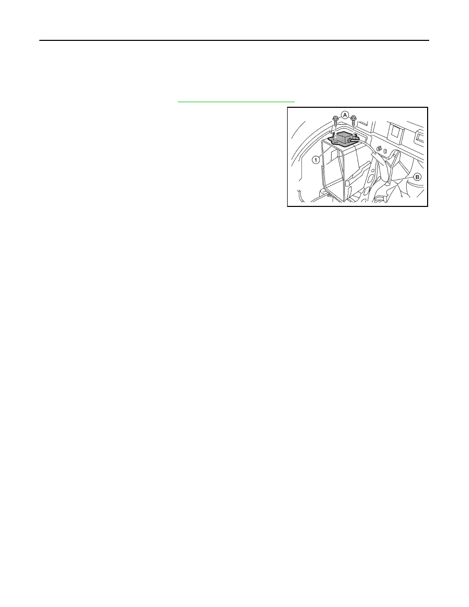
2. Remove the GPS antenna screws (A), detach the GPS antenna

harness clip (B).

3. Remove GPS antenna and feeder assembly (1) out of the instru-

ment panel.

INSTALLATION

Installation is in the reverse order of removal.

ALNIA0378ZZ

August 2012

2012 Pathfinder

AV

SATELLITE RADIO ANTENNA

AV-435

< REMOVAL AND INSTALLATION >

[BOSE AUDIO WITH NAVIGATION]

C

D

E

F

G

H

I

J

K

L

M

B

A

O

P

SATELLITE RADIO ANTENNA

Removal and Installation

INFOID:0000000007347958

REMOVAL

1. Remove the front roof console finisher. Refer to 

INT-22, "Removal and Installation"

.

2. Disconnect the satellite antenna connector.
3. Remove the satellite antenna nut.
4. Remove the satellite antenna.

INSTALLATION

Installation is in the reverse order of removal.

LKIA0679E

August 2012

2012 Pathfinder

AV-436

< REMOVAL AND INSTALLATION >

[BOSE AUDIO WITH NAVIGATION]

STEERING SWITCH

STEERING SWITCH

Removal and Installation

INFOID:0000000007347959

REMOVAL

1. Remove the driver air bag module. Refer to 

SR-5, "Removal and Installation"

.

2. Remove the steering wheel audio control switch assembly screws.
3. Disconnect the steering wheel audio control switches connector. 
4. Remove the steering wheel audio control switches by pulling on

steering wheel audio control switches to release the pawls.

CAUTION:

Do not tilt steering wheel audio control switches during

removal or damage may occur to the pawls.

:  Pawl

INSTALLATION

Installation is in the reverse order of removal.

1. Steering wheel

2.

Steering wheel audio control switches

ALNIA0357ZZ

ALNIA1214ZZ

August 2012

2012 Pathfinder

AV

MICROPHONE

AV-437

< REMOVAL AND INSTALLATION >

[BOSE AUDIO WITH NAVIGATION]

C

D

E

F

G

H

I

J

K

L

M

B

A

O

P

MICROPHONE

Removal and Installation

INFOID:0000000007347960

REMOVAL

1. Remove the front roof console finisher. Refer to 

INT-22, "Removal and Installation"

.

2. Detach the microphone (1) from the front console finisher tabs

(A).

3. Disconnect the microphone connector (B) and remove the

microphone (1).

INSTALLATION

Installation is in the reverse order of removal.

ALNIA0379ZZ

August 2012

2012 Pathfinder

AV-438

< REMOVAL AND INSTALLATION >

[BOSE AUDIO WITH NAVIGATION]

REAR VIEW CAMERA

REAR VIEW CAMERA

Removal and Installation

INFOID:0000000007347961

REMOVAL

1. Remove the license lamp finisher. Refer to 

EXT-23, "Removal and Installation"

.

2. Disconnect the rear view camera connector.
3. Detach the rear view camera harness clip.
4. Detach the rear view camera to release, then pull out to remove the rear view camera while feeding the

rear view camera harness and connector through the back door.

INSTALLATION

Installation is in the reverse order of removal.

1.

Rear view camera

A.

Rear view camera connector

B.

Rear view camera harness clip

ALNIA1182ZZ

August 2012

2012 Pathfinder

BCS

BCS-1

ELECTRICAL & POWER CONTROL

C

D

E

F

G

H

I

J

K

L

B

SECTION 

BCS

A

O

P

N

CONTENTS

BODY CONTROL SYSTEM

BASIC INSPECTION  ....................................

3

INSPECTION AND ADJUSTMENT .....................

3

ADDITIONAL SERVICE WHEN REPLACING 
CONTROL UNIT (BCM) .............................................
..

3

ADDITIONAL SERVICE WHEN REPLACING 
CONTROL UNIT (BCM) : Description .....................
..

3

ADDITIONAL SERVICE WHEN REPLACING 
CONTROL UNIT (BCM) : Work Procedure .............
..

3

CONFIGURATION (BCM)  ...........................................

3

CONFIGURATION (BCM) : Description ....................

4

CONFIGURATION (BCM) : Work Procedure ............

4

CONFIGURATION (BCM) : Configuration List ..........

5

SYSTEM DESCRIPTION  ..............................

6

BODY CONTROL SYSTEM ................................

6

System Description  ...................................................

6

Component Parts Location ........................................

7

COMBINATION SWITCH READING SYSTEM 

.....

8

System Diagram ........................................................

8

System Description  ...................................................

8

Component Parts Location ......................................

11

SIGNAL BUFFER SYSTEM  ...............................

12

System Diagram ......................................................

12

System Description  .................................................

12

POWER CONSUMPTION CONTROL SYS-
TEM ....................................................................

13

System Diagram ......................................................

13

System Description  .................................................

13

Component Parts Location ......................................

15

DIAGNOSIS SYSTEM (BCM)  ............................

16

COMMON ITEM .........................................................

16

COMMON ITEM : CONSULT Function (BCM - 
COMMON ITEM) .....................................................

16

DOOR LOCK ..............................................................

17

DOOR LOCK : CONSULT Function (BCM - 
DOOR LOCK) ..........................................................

17

REAR DEFOGGER ....................................................

18

REAR DEFOGGER : CONSULT Function (BCM - 
REAR DEFOGGER) ................................................

18

BUZZER .....................................................................

18

BUZZER : CONSULT Function (BCM - BUZZER) ....

18

INT LAMP ...................................................................

18

INT LAMP : CONSULT Function (BCM - INT 
LAMP) ......................................................................

18

MULTI REMOTE ENT  ................................................

19

MULTI REMOTE ENT : CONSULT Function 
(BCM - MULTI REMOTE ENT) ................................

19

HEADLAMP ...............................................................

20

HEADLAMP : CONSULT Function (BCM - HEAD 
LAMP) ......................................................................

21

WIPER ........................................................................

22

WIPER : CONSULT Function (BCM - WIPER)  .......

22

FLASHER ...................................................................

22

FLASHER : CONSULT Function (BCM - FLASH-
ER) ..........................................................................

22

AIR CONDITIONER  ...................................................

23

AIR CONDITIONER : CONSULT Function (BCM - 
AIR CONDITIONER)  ...............................................

23

INTELLIGENT KEY ....................................................

23

INTELLIGENT KEY : CONSULT Function (BCM - 
INTELLIGENT KEY)  ................................................

23

COMB SW ..................................................................

23

COMB SW : CONSULT Function (BCM - COMB 
SW) ..........................................................................

23

BCM ...........................................................................

24

BCM : CONSULT Function (BCM - BCM)  ...............

24

August 2012

2012 Pathfinder

BCS-2

IMMU .........................................................................

24

IMMU : CONSULT Function (BCM - IMMU)  ...........

24

BATTERY SAVER  ....................................................

24

BATTERY SAVER : CONSULT Function (BCM - 
BATTERY SAVER) ................................................
.

24

TRUNK ......................................................................

25

TRUNK : CONSULT Function (BCM - TRUNK)  .....

25

THEFT ALM  ..............................................................

25

THEFT ALM : CONSULT Function (BCM - THEFT 
ALM) ......................................................................
.

26

RETAINED PWR  .......................................................

26

RETAINED PWR : CONSULT Function (BCM - 
RETAINED PWR)  ..................................................
.

26

SIGNAL BUFFER ......................................................

27

SIGNAL BUFFER : CONSULT Function (BCM - 
SIGNAL BUFFER) .................................................
.

27

AIR PRESSURE MONITOR ......................................

27

AIR PRESSURE MONITOR : CONSULT Function 
(BCM - AIR PRESSURE MONITOR) ....................
.

27

PANIC ALARM ..........................................................

28

PANIC ALARM : CONSULT Function (BCM - 
PANIC ALARM)  .....................................................
.

28

DTC/CIRCUIT DIAGNOSIS .........................

29

U1000 CAN COMM CIRCUIT  ............................

29

Description ..............................................................

29

DTC Logic ...............................................................

29

Diagnosis Procedure  ..............................................

29

POWER SUPPLY AND GROUND CIRCUIT  .....

30

Diagnosis Procedure  ..............................................

30

COMBINATION SWITCH INPUT CIRCUIT  .......

32

Diagnosis Procedure  ..............................................

32

Special Repair Requirement  ...................................

32

COMBINATION SWITCH OUTPUT CIRCUIT ...

33

Diagnosis Procedure ...............................................

33

Special Repair Requirement  ...................................

34

ECU DIAGNOSIS INFORMATION .............

35

BCM (BODY CONTROL MODULE) ..................

35

Reference Value  .....................................................

35

Terminal Layout  ......................................................

38

Physical Values .......................................................

38

Fail Safe .................................................................

43

DTC Inspection Priority Chart ...............................

43

DTC Index ..............................................................

44

WIRING DIAGRAM  ....................................

46

BCM (BODY CONTROL MODULE) ..................

46

Wiring Diagram  .......................................................

46

SYMPTOM DIAGNOSIS  ............................

50

COMBINATION SWITCH SYSTEM SYMP-
TOMS .................................................................

50

Symptom Table .......................................................

50

PRECAUTION ............................................

51

PRECAUTIONS  .................................................

51

Precaution for Supplemental Restraint System 
(SRS) "AIR BAG" and "SEAT BELT PRE-TEN-
SIONER" .................................................................

51

Precaution Necessary for Steering Wheel Rota-
tion After Battery Disconnect  ..................................

51

REMOVAL AND INSTALLATION ..............

53

BCM (BODY CONTROL MODULE) ..................

53

Removal and Installation .........................................

53

August 2012

2012 Pathfinder

BCS

INSPECTION AND ADJUSTMENT

BCS-3

< BASIC INSPECTION >

C

D

E

F

G

H

I

J

K

L

B

A

O

P

N

BASIC INSPECTION

INSPECTION AND ADJUSTMENT

ADDITIONAL SERVICE WHEN REPLACING CONTROL UNIT (BCM)
ADDITIONAL SERVICE WHEN REPLACING CONTROL UNIT (BCM) : Description

INFOID:0000000007354898

BEFORE REPLACEMENT

When replacing BCM, save or print current vehicle specification with CONSULT configuration before replace-

ment.

NOTE:

If “Before Replace ECU” cannot be used, use the “After Replace ECU” or “Manual Configuration” after replac-

ing BCM.

AFTER REPLACEMENT

CAUTION:

• When replacing BCM, you must perform “After Replace ECU” with CONSULT.

- Complete the procedure of “After Replace ECU” in order.

- If you set incorrect “After Replace ECU”, incidents might occur.

- Configuration is different for each vehicle model. Confirm configuration of each vehicle model.

• When replacing BCM, perform the system initialization (NATS).

ADDITIONAL SERVICE WHEN REPLACING CONTROL UNIT (BCM) : Work Proce-
dure

INFOID:0000000007354899

1.

SAVING VEHICLE SPECIFICATION

CONSULT

Enter "Re/Programming, Configuration" and perform “Before Replace ECU” to save or print current vehicle

specification.

NOTE:

If “Before Replace ECU” cannot be used, use the "After Replace ECU" or "Manual Configuration" after replac-

ing BCM.

>> GO TO 2.

2.

REPLACE BCM

Replace BCM. Refer to 

BCS-53, "Removal and Installation"

.

>> GO TO 3.

3.

WRITING VEHICLE SPECIFICATION

CONSULT

1. Enter "Re/Programming, Configuration".

2. If “Before Replace ECU” operation was performed, automatically an "Operation Log Selection" screen will

be displayed. Select the applicable file from the "Saved Data List" and press “Confirm” to write vehicle

specification. Refer to 

BCS-4, "CONFIGURATION (BCM) : Work Procedure"

.

3. If “Before Replace ECU” operation was not performed, select "After Replace ECU" or "Manual Configura-

tion" to write vehicle specification. Refer to 

BCS-4, "CONFIGURATION (BCM) : Work Procedure"

.

>> GO TO 4.

4.

INITIALIZE BCM (NATS)

Perform BCM initialization. (NATS)

>> Work End.

CONFIGURATION (BCM)

August 2012

2012 Pathfinder


Content      ..     75      76      77      78     ..