Nissan Pathfinder (2012 year). Manual - part 57


  Index      Manuals     Nissan Pathfinder (2012 year) - Service and Repair Manual


Search            copyright infringement  


Content      ..     55      56      57      58     ..


Nissan Pathfinder (2012 year). Manual - part 57


AV-274

< REMOVAL AND INSTALLATION >

[BOSE AUDIO WITHOUT NAVIGATION]

REAR VIEW CAMERA

REAR VIEW CAMERA

Removal and Installation

INFOID:0000000007347809
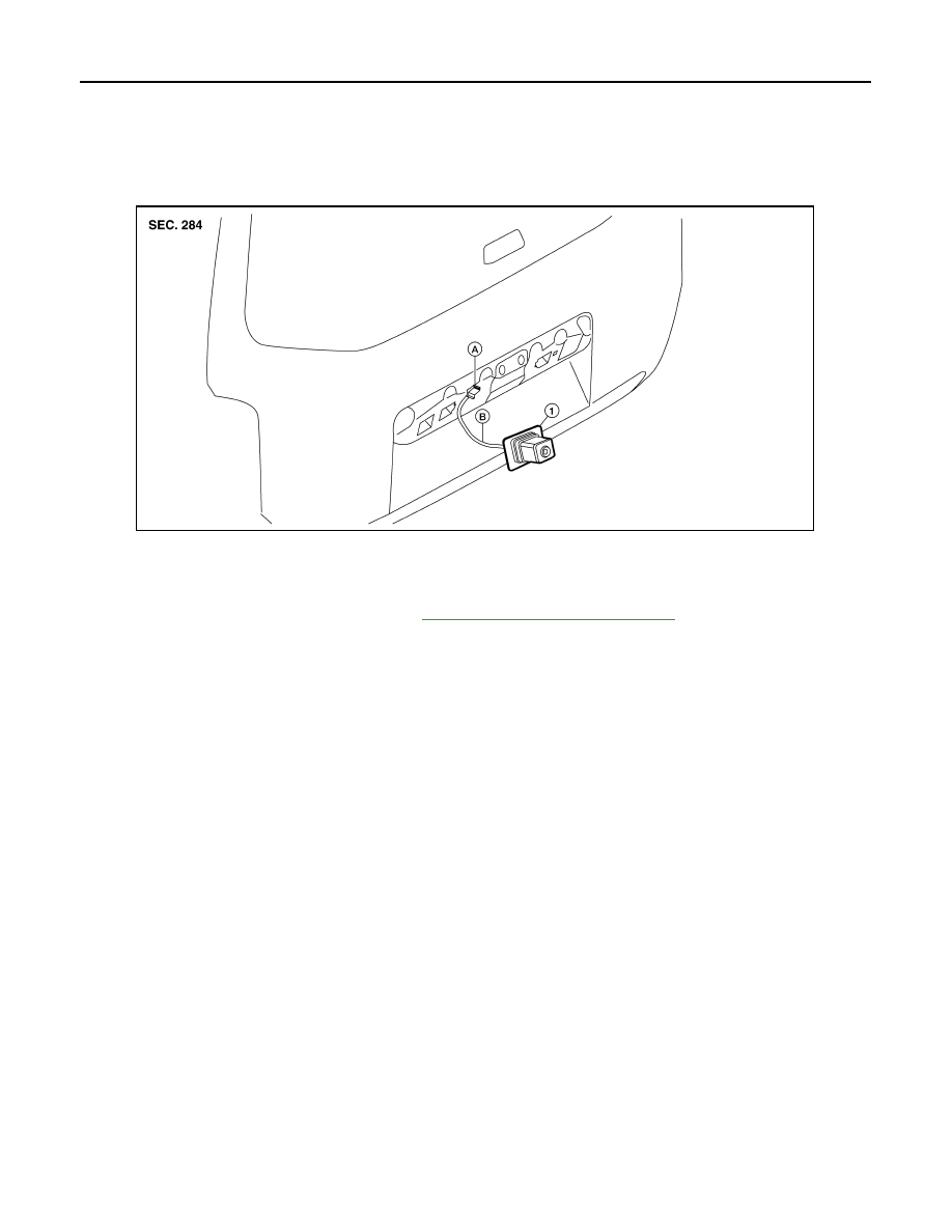
REMOVAL

1. Remove the license lamp finisher. Refer to 

EXT-23, "Removal and Installation"

.

2. Disconnect the rear view camera connector.
3. Detach the rear view camera harness clip.
4. Detach the rear view camera to release, then pull out to remove the rear view camera while feeding the

rear view camera harness and connector through the back door.

INSTALLATION

Installation is in the reverse order of removal.

1.

Rear view camera

A.

Rear view camera connector

B.

Rear view camera harness clip

ALNIA1182ZZ

August 2012

2012 Pathfinder

AV

DIAGNOSIS AND REPAIR WORKFLOW

AV-275

< BASIC INSPECTION >

[BOSE AUDIO WITH NAVIGATION]

C

D

E

F

G

H

I

J

K

L

M

B

A

O

P

BASIC INSPECTION

DIAGNOSIS AND REPAIR WORKFLOW

Work Flow

INFOID:0000000007347810

OVERALL SEQUENCE

• Reference 1··· Refer to 

AV-306, "AV CONTROL UNIT : CONSULT Function"

.

• Reference 2··· Refer to 

AV-407, "Symptom Table"

.

DETAILED FLOW

1.

CHECK SYMPTOM

Check the malfunction symptoms by performing the following items. 

• Interview the customer to obtain the malfunction information (conditions and environment when the malfunc-

tion occurred).

• Check the symptom. 

>> GO TO 2

2.

SELF-DIAGNOSIS (CONSULT)

1. Connect CONSULT and perform “SELF-DIAGNOSIS” for “MULTI AV”.

NOTE:

Skip to step 4 of the diagnosis procedure if “MULTI AV” is not displayed.

2. Check if any DTC No. is displayed in the self-diagnosis results.

AWNIA2357GB

August 2012

2012 Pathfinder

AV-276

< BASIC INSPECTION >

[BOSE AUDIO WITH NAVIGATION]

DIAGNOSIS AND REPAIR WORKFLOW

Is any DTC displayed?

YES

>> GO TO 3

NO

>> GO TO 4

3.

CHECK SELF-DIAGNOSIS RESULTS (CONSULT)

1. Check the DTC No. indicated in the self-diagnosis results.

2. Perform the relevant diagnosis referring to the DTC No. list. Refer to 

AV-376, "DTC Index"

.

NOTE:

Start with the diagnosis for the CAN communication system if “CAN COMM CIRCUIT [U1000] or CONTROL

UNIT (CAN) [U1010]” is displayed.

>> GO TO 5

4.

PERFORM DIAGNOSIS BY SYMPTOM

Perform the relevant diagnosis referring to the diagnosis chart by symptom. Refer to 

AV-407, "Symptom

Table"

.

>> GO TO 5

5.

REPAIR OR REPLACE MALFUNCTIONING PARTS

Repair or replace the identified malfunctioning parts.

NOTE:

Erase the stored self-diagnosis results after repairing or replacing the relevant components if any DTC No. has

been indicated in the self-diagnosis results. 

>> GO TO 6

6.

CHECK AFTER REPAIR

1. Perform self-diagnosis for “MULTI AV” with CONSULT after repairing or replacing the malfunctioning

parts.

2. Check if any DTC No. is displayed in the self-diagnosis results.
Is any DTC displayed?

YES

>> GO TO 3

NO

>> GO TO 7

7.

FINAL CHECK

Perform the operation check to confirm that the malfunction symptom is solved or that any other symptoms

are present.
Are any symptoms present?

YES

>> GO TO 4

NO

>> Inspection End.

August 2012

2012 Pathfinder

AV

AUDIO SYSTEM

AV-277

< SYSTEM DESCRIPTION >

[BOSE AUDIO WITH NAVIGATION]

C

D

E

F

G

H

I

J

K

L

M

B

A

O

P

SYSTEM DESCRIPTION

AUDIO SYSTEM

System Diagram

INFOID:0000000007347811

System Description

INFOID:0000000007347812

AUDIO SYSTEM

AWNIA2300GB

August 2012

2012 Pathfinder

AV-278

< SYSTEM DESCRIPTION >

[BOSE AUDIO WITH NAVIGATION]

AUDIO SYSTEM

The audio system consists of the following components

• AV control unit

• Display unit

• BOSE speaker amp.

• Window antenna

• Steering wheel audio control switches

• A/C and AV switch assembly

• Front door speakers

• Front tweeters

• Rear door speakers

• Rear tweeters

• Subwoofer

When the audio system is on, radio signals are received by the window antenna. The AV control unit then

sends audio signals to the BOSE speaker amp. The BOSE speaker amp. amplifies the audio signals before

sending them to the front door speakers, front tweeters, rear door speakers, rear tweeters and the subwoofer.

Refer to Owner's Manual for audio system operating instructions.

SATELLITE RADIO SYSTEM

The satellite radio system consists of the following components

• Satellite antenna

• AV control unit

When the satellite radio system is on, radio signals are supplied to the AV control unit from the satellite

antenna. The AV control unit then sends audio signals to the BOSE speaker amp.

Refer to Owner's Manual for satellite radio system operating instructions.

SPEED SENSITIVE VOLUME SYSTEM

Volume level of this system goes up and down automatically in proportion to the vehicle speed. The control

level can be selected by the customer. Refer to Owner's Manual for operating instructions.

August 2012

2012 Pathfinder

AV

AUDIO SYSTEM

AV-279

< SYSTEM DESCRIPTION >

[BOSE AUDIO WITH NAVIGATION]

C

D

E

F

G

H

I

J

K

L

M

B

A

O

P

Component Parts Location

INFOID:0000000007347813

1.

Steering wheel audio control switch-
es

2.

Front tweeter LH M109

3.

AV control unit M23, M37, M39, M44, 
M48, M71, M72 

4.

A/C and AV switch assembly M98

5.

Display unit M92

6.

Front tweeter RH M111

AWNIA2301ZZ

August 2012

2012 Pathfinder

AV-280

< SYSTEM DESCRIPTION >

[BOSE AUDIO WITH NAVIGATION]

AUDIO SYSTEM

Component Description

INFOID:0000000007347814

7.

Aux. jack M85

8.

Compact Flash insert slot

9.

Front door speaker
LH D12
RH D112

10. Rear door speaker

LH D207
RH D307

11. Rear tweeter

LH D208
RH D308

12. Subwoofer B72

13. BOSE speaker amp B74, B75 (locat-

ed under driver seat)

14. Rear view camera  D551

15. Microphone R8

Part name

Description

AV control unit

Controls audio system and satellite radio system functions

Display unit

• Touch screen controls all audio and A/C operations
• Displays all audio and climate control related information

BOSE speaker amp.

Receives power (amp ON) and audio signals from AV control unit and out-
puts audio signals to each speaker.

Steering wheel audio control switches

• Audio operation can be operated
• Steering wheel audio control switch signal is output to AV control unit

Front door speakers

• Outputs audio signal from BOSE speaker amp.
• Outputs high, mid and low range sounds

Front tweeters

• Outputs audio signal from BOSE speaker amp.
• Outputs high range sounds

Rear door speakers

• Outputs audio signal from BOSE speaker amp.
• Outputs high, mid and low range sounds

Rear tweeters

• Outputs audio signal from BOSE speaker amp.
• Outputs high range sounds

Subwoofer

• Outputs audio signal from BOSE speaker amp.
• Outputs low range sounds

Satellite antenna

Audio signal (satellite radio) is received and output to AV control unit.

August 2012

2012 Pathfinder

AV

NAVIGATION SYSTEM

AV-281

< SYSTEM DESCRIPTION >

[BOSE AUDIO WITH NAVIGATION]

C

D

E

F

G

H

I

J

K

L

M

B

A

O

P

NAVIGATION SYSTEM

System Diagram

INFOID:0000000007347815

System Description

INFOID:0000000007347816

NOTE:

Refer to NAVIGATION System Owner's Manual for system operation.

The navigation system periodically calculates the vehicle's current position according to the following three

signals: Travel distance of the vehicle as determined by the vehicle speed sensor, turning angle of the vehicle

as determined by the gyroscope (angular velocity sensor), and the direction of vehicle travel as determined by

the GPS antenna (GPS information).

The current position of the vehicle is then identified by comparing the calculated vehicle position with map data

read from the map data, which is stored in the hard disk drive (HDD) (map-matching), and indicated on the

screen with a current-location mark.

By comparing the vehicle position detection results found by the

GPS and by map-matching, more accurate vehicle position data can

be used.

The current vehicle position will be calculated by detecting the dis-

tance the vehicle moved from the previous calculation point and its

direction.

TRAVEL DISTANCE 

Travel distance calculations are based on the vehicle speed input signal. Therefore, the calculation may

become incorrect as the tires wear down. To prevent this, an automatic distance fine adjustment function has

been adopted.

TRAVEL DIRECTION 

Change in the travel direction of the vehicle is calculated by a gyroscope (angular velocity sensor) and a GPS

antenna (GPS information). As the gyroscope and GPS antenna have both merit and demerit, input signals

from them are prioritized in each situation. However, this order of priority may change in accordance with more

detailed travel conditions so that the travel direction is detected more accurately.

ALNIA0424GB

SEL684V

August 2012

2012 Pathfinder


Content      ..     55      56      57      58     ..