Nissan Pathfinder (2010 year). Manual - part 615


  Index      Manuals     Nissan Pathfinder (2010 year) - Service and Repair Manual


Search            copyright infringement  


Content      ..     613      614      615      616     ..


Nissan Pathfinder (2010 year). Manual - part 615


TM-48

< COMPONENT DIAGNOSIS >

P0615 STARTER RELAY

2.

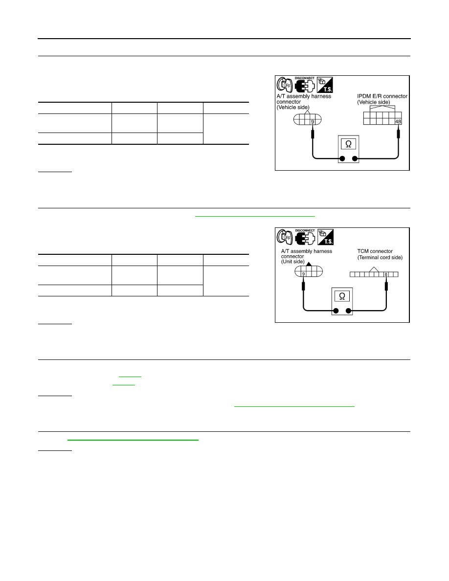
 CHECK HARNESS BETWEEN A/T ASSEMBLY HARNESS CONNECTOR AND IPDM E/R CONNECTOR

1. Turn ignition switch OFF.

2. Disconnect A/T assembly harness connector and IPDM E/R connector.

3. Check continuity between A/T assembly harness connector and

IPDM E/R connector.

4. If OK, check harness for short to ground and short to power.

5. Reinstall any part removed.
OK or NG

OK

>> GO TO 3.

NG

>> Repair open circuit or short to ground or short to power in harness or connectors.

3.

CHECK TERMINAL CORD ASSEMBLY

1. Remove control valve with TCM. Refer to 

TM-174, "Removal and Installation"

.

2. Disconnect A/T assembly harness connector and TCM connector.

3. Check continuity between A/T assembly harness connector ter-

minal and TCM connector terminal.

4. If OK, check harness for short to ground and short to power.

5. Reinstall any part removed.
OK or NG

OK

>> GO TO 4.

NG

>> Replace open circuit or short to ground and short to power in harness or connectors.

4.

DETECT MALFUNCTIONING ITEM

Check the following.

• Starter relay, Refer to 

STR-5

.

• IPDM E/R, Refer to 

PCS-6

.

OK or NG

OK

>> Replace the control valve with TCM. Refer to 

TM-174, "Removal and Installation"

.

NG

>> Repair or replace damaged parts.

5.

CHECK DTC

Perform 

TM-47, "DTC Confirmation Procedure"

.

OK or NG

OK

>>

INSPECTION END

NG

>> GO TO 2.

Item

 Connector

Terminal

Continuity

A/T assembly harness 
connector

F9

9

Yes

IPDM E/R connector

E122

48

SCIA6254E

Item

 Connector

Terminal

Continuity

A/T assembly harness 
connector

F9

9

Yes

TCM connector 

F502

8

SCIA5440E

2010 Pathfinder

P0700 TRANSMISSION CONTROL

TM-49

< COMPONENT DIAGNOSIS >

C

E

F

G

H

I

J

K

L

M

A

B

TM

N

O

P

P0700 TRANSMISSION CONTROL

Description

INFOID:0000000005257980

The TCM consists of a microcomputer and connectors for signal input and output and for power supply. The

TCM controls the A/T.

On Board Diagnosis Logic

INFOID:0000000005257981

• This is an OBD-II self-diagnostic item. 

• Diagnostic trouble code “P0700” with CONSULT-III is detected when the TCM is malfunctioning.

Possible Cause

INFOID:0000000005257982

TCM.

DTC Confirmation Procedure

INFOID:0000000005257983

NOTE:

If “DTC Confirmation Procedure” has been previously performed, always turn ignition switch “OFF”

and wait at least 10 seconds before performing the next test.

After the repair, perform the following procedure to confirm the malfunction is eliminated.

 WITH CONSULT-III

1. Turn ignition switch “ON”. (Do not start engine.)

2. Select “DATA MONITOR” mode for “TRANSMISSION” with CONSULT-III.

3. Start engine.

4. Run engine for at least 2 consecutive seconds at idle speed.

5. If DTC is detected, go to 

TM-49, "Diagnosis Procedure"

.

 WITH GST

Follow the procedure “WITH CONSULT-III”.

Diagnosis Procedure

INFOID:0000000005257984

1.

CHECK DTC

With CONSULT-III

1. Turn ignition switch “ON”. (Do not start engine.)

2. Select “SELF DIAG RESULTS” mode for “TRANSMISSION” with CONSULT-III.

3. Touch “ERASE”.

4. Turn ignition switch “OFF” and wait at least 10 seconds.

5. Perform 

TM-49, "DTC Confirmation Procedure"

.

Is the “P0700” displayed again?

YES

>> Replace the control valve with TCM. Refer to 

TM-174, "Removal and Installation"

.

NO

>>

INSPECTION END

2010 Pathfinder

TM-50

< COMPONENT DIAGNOSIS >

P0705 TRANSMISSION RANGE SWITCH A

P0705 TRANSMISSION RANGE SWITCH A

Description

INFOID:0000000005257985

The transmission range switch detects the selector lever position and sends a signal to the TCM.

CONSULT-III Reference Value in Data Monitor Mode

INFOID:0000000005257986

On Board Diagnosis Logic

INFOID:0000000005257987

• This is an OBD-II self-diagnostic item.

• Diagnostic trouble code “P0705” with CONSULT-III or 9th judgment flicker without CONSULT-III is detected

under the following conditions.

- When TCM does not receive the correct voltage signal from the transmission range switch 1, 2, 3, 4 based

on the gear position.

- When no other position but “P” position is detected from “N” positions.

Possible Cause

INFOID:0000000005257988

• Harness or connectors

(The transmission range switch 1, 2, 3, 4 and TCM circuit is open or shorted.)

• Transmission range switch 1, 2, 3, 4 

DTC Confirmation Procedure

INFOID:0000000005257989

CAUTION:

Always drive vehicle at a safe speed.

NOTE:

If “DTC Confirmation Procedure” has been previously performed, always turn ignition switch “OFF”

and wait at least 10 seconds before performing the next test.

After the repair, perform the following procedure to confirm the malfunction is eliminated.

 WITH CONSULT-III

1. Turn ignition switch “ON”. (Do not start engine.)

2. Select “DATA MONITOR” mode for “TRANSMISSION” with CONSULT-III.

3. Start engine.

4. Drive vehicle and maintain the following conditions for at least 2 consecutive seconds.

ACCELE POSI: More than 1.0/8

5. If DTC is detected, go to 

TM-50, "Diagnosis Procedure"

.

 WITH GST

Follow the procedure “WITH CONSULT-III”.

Diagnosis Procedure

INFOID:0000000005257990

1.

CHECK TRANSMISSION RANGE SWITCH CIRCUIT

With CONSULT-III

1. Turn ignition switch ON. (Do not start engine.)

2. Select “SELECTION FROM MENU” in “DATA MONITOR” mode for “TRANSMISSION” with CONSULT-III.

3. Check if correct selector lever position (N/P, R, D, 3, 2 or 1) is displayed as selector lever is moved into

each position.

Item name

Condition 

Display value

SLCTLVR POSI

 Selector lever in “N”,“P” positions.

N/P

Selector lever in “R” position.

R

Selector lever in “D” position.

D

Selector lever in “3” position.

3

Selector lever in “2” position.

2

Selector lever in “1” position.

1

2010 Pathfinder

P0705 TRANSMISSION RANGE SWITCH A

TM-51

< COMPONENT DIAGNOSIS >

C

E

F

G

H

I

J

K

L

M

A

B

TM

N

O

P

OK or NG

OK

>> GO TO 5.

NG

>> GO TO 2.

2.

CHECK TCM POWER SUPPLY AND GROUND CIRCUIT

Check TCM power supply and ground circuit. Refer to 

TM-100, "Diagnosis Procedure"

.

OK or NG

OK

>> GO TO 3.

NG

>> Repair or replace damaged parts.

3.

DETECT MALFUNCTIONING ITEM

Check the following.

• A/T assembly harness connector pin terminals for damage or loose connection with harness connector.
OK or NG

OK

>> GO TO 4.

NG

>> Repair or replace damaged parts.

4.

CHECK SUB-HARNESS

1. Remove control valve with TCM. Refer to 

TM-174, "Removal and Installation"

.

2. Disconnect transmission range switch connector and TCM connector.

3. Check continuity between transmission range switch connector

(A) terminals and TCM connector (B) terminals.

4. If OK, check harness for short to ground and short to power.

5. Reinstall any part removed.
OK or NG

OK

>> Replace the control valve with TCM. Refer to 

TM-174, "Removal and Installation"

.

NG

>> Replace open circuit or short to ground and short to power in harness or connectors.

5.

CHECK DTC

Perform “DTC Confirmation Procedure”.

• Refer to 

TM-50, "DTC Confirmation Procedure"

.

OK or NG

OK

>>

INSPECTION END

NG

>> GO TO 2.

Item

 Connector

Terminal

Continuity

Transmission range switch con-
nector

F505

1

Yes

TCM connector 

F503

13

Transmission range switch con-
nector

F505

2

Yes

TCM connector 

F503

11

Transmission range switch con-
nector

F505

3

Yes

TCM connector 

F503

12

Transmission range switch con-
nector

F505

5

Yes

TCM connector 

F503

14

JSDIA1328GB

2010 Pathfinder

TM-52

< COMPONENT DIAGNOSIS >

P0717 INPUT SPEED SENSOR A

P0717 INPUT SPEED SENSOR A

Description

INFOID:0000000005257991

The input speed sensor detects input shaft rpm (revolutions per minute). It is located on the input side of the

automatic transmission. Monitors revolution of sensor 1 and sensor 2 for non-standard conditions.

CONSULT-III Reference Value in Data Monitor Mode

INFOID:0000000005257992

On Board Diagnosis Logic

INFOID:0000000005257993

• This is an OBD-II self-diagnostic item. 

• Diagnostic trouble code “P0717” with CONSULT-III or 11th judgment flicker without CONSULT-III is detected

under the following conditions.

- When TCM does not receive the proper voltage signal from the sensor.

- When TCM detects an irregularity only at position of 4GR for input speed sensor 2.

Possible Cause

INFOID:0000000005257994

• Harness or connectors

(The sensor circuit is open or shorted.)

• Input speed sensor 1, 2

DTC Confirmation Procedure

INFOID:0000000005257995

CAUTION:

• Always drive vehicle at a safe speed.

• Be careful not to rev engine into the red zone on the tachometer.

NOTE:

If “DTC Confirmation Procedure” has been previously performed, always turn ignition switch “OFF”

and wait at least 10 seconds before performing the next test.

After the repair, perform the following procedure to confirm the malfunction is eliminated.

 WITH CONSULT-III

1. Turn ignition switch “ON”. (Do not start engine.)

2. Select “DATA MONITOR” mode for “TRANSMISSION” with CONSULT-III.

3. Start engine and maintain the following conditions for at least 5 consecutive seconds.

VHCL/S SE-A/T: 40 km/h (25 MPH) or more

ENGINE SPEED: 1,500 rpm or more

ACCELE POSI: 0.5/8 or more

SLCT LVR POSI: “D” position

GEAR (Input speed sensor 1): 4th or 5th position

GEAR (Input speed sensor 2): All position

Driving location: Driving the vehicle uphill (increased engine load) will help maintain the driving

conditions required for this test.

4. If DTC is detected, go to 

TM-52, "Diagnosis Procedure"

.

 WITH GST

Follow the procedure “WITH CONSULT-III”.

Diagnosis Procedure

INFOID:0000000005257996

1.

CHECK INPUT SIGNAL

With CONSULT-III

1. Start engine.

2. Select “ECU INPUT SIGNALS” in “DATA MONITOR” mode for “TRANSMISSION” with CONSULT-III.

3. Vehicle start and read out the value of “INPUT SPEED”.

Item name

Condition 

Display value (rpm)

INPUT SPEED

During driving (lock-up ON)

Approximately matches the engine speed.

2010 Pathfinder

P0717 INPUT SPEED SENSOR A

TM-53

< COMPONENT DIAGNOSIS >

C

E

F

G

H

I

J

K

L

M

A

B

TM

N

O

P

OK or NG

OK

>> GO TO 4.

NG

>> GO TO 2.

2.

CHECK TCM POWER SUPPLY AND GROUND CIRCUIT

Check TCM power supply and ground circuit. Refer to 

TM-100, "Diagnosis Procedure"

.

OK or NG

OK

>> GO TO 3.

NG

>> Repair or replace damaged parts.

3.

DETECT MALFUNCTIONING ITEM

Check the following.

• The A/T assembly harness connector pin terminals for damage or loose connection with harness connector.
OK or NG

OK

>> Replace the control valve with TCM. Refer to 

TM-174, "Removal and Installation"

.

NG

>> Repair or replace damaged parts.

4.

CHECK DTC

Perform “DTC Confirmation Procedure”.

• Refer to 

TM-52, "DTC Confirmation Procedure"

.

OK or NG

OK

>>

INSPECTION END

NG

>> GO TO 2.

2010 Pathfinder

TM-54

< COMPONENT DIAGNOSIS >

P0720 OUTPUT SPEED SENSOR

P0720 OUTPUT SPEED SENSOR

Description

INFOID:0000000005257997

The output speed sensor detects the revolution of the parking gear and emits a pulse signal. The pulse signal

is sent to the TCM which converts it into vehicle speed.

CONSULT-III Reference Value in Data Monitor Mode

INFOID:0000000005257998

On Board Diagnosis Logic

INFOID:0000000005257999

• This is an OBD-II self-diagnostic item.

• Diagnostic trouble code “P0720” with CONSULT-III or 1st judgment flicker without CONSULT-III is detected

under the following conditions.

- When TCM does not receive the proper voltage signal from the sensor.

- After ignition switch is turned “ON”, irregular signal input from vehicle speed signal before the vehicle starts

moving.

Possible Cause

INFOID:0000000005258000

• Harness or connectors

(The sensor circuit is open or shorted.)

• Output speed sensor

• Vehicle speed signal

DTC Confirmation Procedure

INFOID:0000000005258001

CAUTION:

• Always drive vehicle at a safe speed.

• Be careful not to rev engine into the red zone on the tachometer.

NOTE:

If “DTC Confirmation Procedure” has been previously performed, always turn ignition switch “OFF”

and wait at least 10 seconds before performing the next test.

After the repair, perform the following procedure to confirm the malfunction is eliminated.

 WITH CONSULT-III

1. Turn ignition switch “ON”. (Do not start engine.)

2. Select “DATA MONITOR” mode for “TRANSMISSION” with CONSULT-III.

3. Drive vehicle and check for an increase of “VHCL/S SE-A/T” value in response to “VHCL/S SE-MTR”

value.

If the check result is NG, go to 

TM-55, "Diagnosis Procedure"

.

If the check result is OK, go to following step.

4. Select “DATA MONITOR” mode for “TRANSMISSION” with CONSULT-III.

5. Start engine and maintain the following conditions for at least 5 consecutive seconds.

VHCL/S SE-A/T: 30 km/h (19 MPH) or more

ACCELE POSI: More than 1.0/8

SLCT LVR POSI: “D” position 

Driving location: Driving the vehicle uphill (increased engine load) will help maintain the driving

conditions required for this test.

If the check result is NG, go to 

TM-55, "Diagnosis Procedure"

.

If the check result is OK, go to following step.

6. Maintain the following conditions for at least 5 consecutive seconds.

ENGINE SPEED: 3,500 rpm or more

ACCELE POSI: More than 1.0/8

SLCT LVR POSI: “D” position

Driving location: Driving the vehicle uphill (increased engine load) will help maintain the driving

conditions required for this test.

If the check result is NG, go to 

TM-55, "Diagnosis Procedure"

.

Item name

Condition 

Display value (km/h)

VHCL/S SE-A/T

During driving

 Approximately matches the speedometer reading.

2010 Pathfinder

P0720 OUTPUT SPEED SENSOR

TM-55

< COMPONENT DIAGNOSIS >

C

E

F

G

H

I

J

K

L

M

A

B

TM

N

O

P

 WITH GST

Follow the procedure “WITH CONSULT-III”.

Diagnosis Procedure

INFOID:0000000005258002

1.

CHECK INPUT SIGNAL

With CONSULT-III

1. Turn ignition switch ON.

2. Select “ECU INPUT SIGNALS” in “DATA MONITOR” mode for “TRANSMISSION” with CONSULT-III.

3. Start the engine.

4. Read out the value of “VHCL/S SE-A/T” while driving.

Check the value changes according to driving speed.

OK or NG

OK

>> GO TO 6.

NG

>> GO TO 2.

2.

CHECK TCM POWER SUPPLY AND GROUND CIRCUIT

Check TCM power supply and ground circuit. Refer to 

TM-100, "Diagnosis Procedure"

.

OK or NG

OK

>> GO TO 3.

NG

>> Repair or replace damaged parts.

3.

DETECT MALFUNCTIONING ITEM

Check the following.

• The A/T assembly harness connector pin terminals for damage or loose connection with harness connector.
OK or NG

OK

>> GO TO 4.

NG

>> Repair or replace damaged parts.

4.

CHECK SUB-HARNESS

1. Remove control valve with TCM. Refer to 

TM-174, "Removal and Installation"

.

2. Disconnect transmission range switch connector and TCM connector.

3. Check continuity between transmission range switch connector

(A) terminals and TCM connector (B) terminals.

4. If OK, check harness for short to ground and short to power.

5. Reinstall any part removed.
OK or NG

OK

>> GO TO 5.

NG

>> Replace open circuit or short to ground and short to power in harness or connectors.

5.

REPLACE THE OUTPUT SPEED SENSOR AND CHECK DTC

1. Replace the output speed sensor. Refer to 

TM-217

.

2. Perform “DTC Confirmation Procedure”. Refer to 

TM-54, "DTC Confirmation Procedure"

.

OK or NG

Item

 Connector

Terminal

Continuity

Transmission range switch con-
nector

F505

8

Yes

TCM connector 

F503

20

Transmission range switch con-
nector

F505

9

Yes

TCM connector 

F503

17

Transmission range switch con-
nector

F505

10

Yes

TCM connector 

F503

16

JSDIA1329GB

2010 Pathfinder


Content      ..     613      614      615      616     ..