Nissan Pathfinder (2010 year). Manual - part 613


  Index      Manuals     Nissan Pathfinder (2010 year) - Service and Repair Manual


Search            copyright infringement  


Content      ..     611      612      613      614     ..


Nissan Pathfinder (2010 year). Manual - part 613


TM-32

< FUNCTION DIAGNOSIS >

A/T SHIFT LOCK SYSTEM

A/T SHIFT LOCK SYSTEM

System Description

INFOID:0000000005257958

• The selector lever cannot be shifted from “P” (Park) unless the brake pedal is depressed and the ignition

switch is in the “ON” position.

• Battery voltage is supplied to the shift lock solenoid by the stop lamp switch.

• Ground is supplied to the shift lock solenoid by the park position switch (shift selector).

• With the the ignition switch “ON”, brake pedal depressed and the A/T shift selector in “P” (Park), the shift

lock solenoid is energized, allowing the selector lever to be shifted from Park.

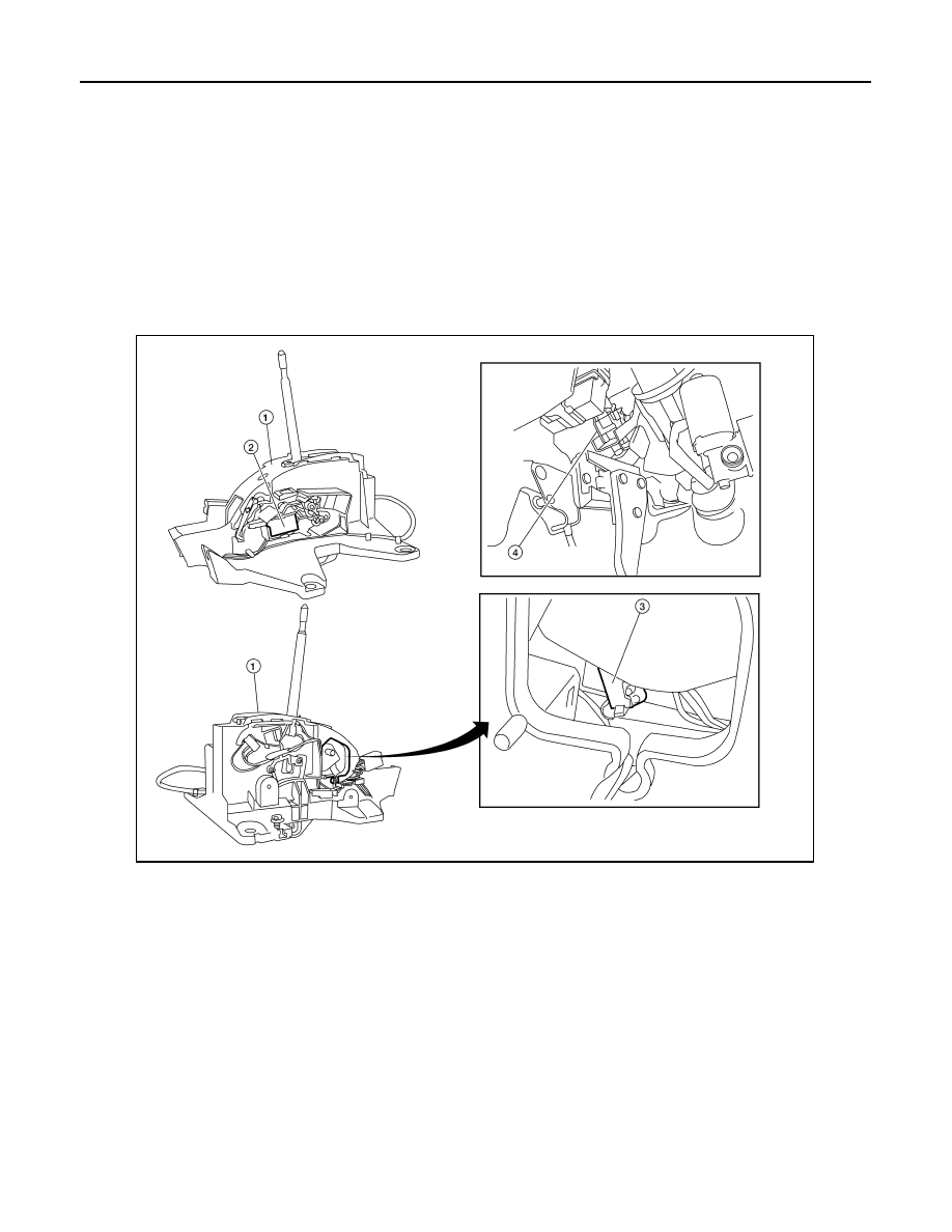
Component Parts Location (With Manual Mode)

INFOID:0000000005257959

1.

A/T shift selector

2.

Shift lock solenoid

3.

Park position switch (shift selector)

4.

Stop lamp switch E38

AWDIA0736GB

2010 Pathfinder

A/T SHIFT LOCK SYSTEM

TM-33

< FUNCTION DIAGNOSIS >

C

E

F

G

H

I

J

K

L

M

A

B

TM

N

O

P

Component Parts Location (Without Manual Mode)

INFOID:0000000005257961

1.

A/T shift selector

2.

Shift lock solenoid

3.

Park position switch (shift selector)

4.

Stop lamp switch E38

AWDIA0735GB

2010 Pathfinder

TM-34

< FUNCTION DIAGNOSIS >

ON BOARD DIAGNOSTIC (OBD) SYSTEM

ON BOARD DIAGNOSTIC (OBD) SYSTEM

Introduction

INFOID:0000000005257962

The A/T system has two self-diagnostic systems.

The first is the emission-related on board diagnostic system (OBD-II) performed by the TCM in combination

with the ECM. The malfunction is indicated by the MIL (malfunction indicator lamp) and is stored as a DTC in

the ECM memory but not the TCM memory.

The second is the TCM original self-diagnosis indicated by the A/T CHECK indicator lamp. The malfunction is

stored in the TCM memory. The detected items are overlapped with OBD-II self-diagnostic items. For detail,

refer to 

TM-36, "CONSULT-III Function (TRANSMISSION)"

.

OBD-II Function for A/T System

INFOID:0000000005257963

The ECM provides emission-related on board diagnostic (OBD-II) functions for the A/T system. One function

is to receive a signal from the TCM used with OBD-related parts of the A/T system. The signal is sent to the

ECM when a malfunction occurs in the corresponding OBD-related part. The other function is to indicate a

diagnostic result by means of the MIL (malfunction indicator lamp) on the instrument panel. Sensors, switches

and solenoid valves are used as sensing elements.

The MIL automatically illuminates in One or Two Trip Detection Logic when a malfunction is sensed in relation

to A/T system parts.

One or Two Trip Detection Logic of OBD-II

INFOID:0000000005257964

ONE TRIP DETECTION LOGIC

If a malfunction is sensed during the first test drive, the MIL will illuminate and the malfunction will be stored in

the ECM memory as a DTC. The TCM is not provided with such a memory function.

TWO TRIP DETECTION LOGIC

When a malfunction is sensed during the first test drive, it is stored in the ECM memory as a 1st trip DTC

(diagnostic trouble code) or 1st trip freeze frame data. At this point, the MIL will not illuminate. — 1st Trip

If the same malfunction as that experienced during the first test drive is sensed during the second test drive,

the MIL will illuminate. — 2nd Trip

The “Trip” in the “One or Two Trip Detection Logic” means a driving mode in which self-diagnosis is performed

during vehicle operation.

OBD-II Diagnostic Trouble Code (DTC)

INFOID:0000000005257965

HOW TO READ DTC AND 1ST TRIP DTC

DTC and 1st trip DTC can be read by the following methods.

(  with CONSULT-III or   GST)

 CONSULT-III or GST (Generic Scan Tool) Examples: P0705, P0720 etc.

These DTC are prescribed by SAE J2012.

(CONSULT-III also displays the malfunctioning component or system.)

1st trip DTC No. is the same as DTC No.

Output of the diagnostic trouble code indicates that the indicated circuit has a malfunction. How-

ever, in case of the Mode II and GST, they do not indicate whether the malfunction is still occurring or

occurred in the past and returned to normal.

CONSULT-III can identify them as shown below, therefore, CONSULT-III (if available) is recom-

mended.

Freeze Frame Data and 1st Trip Freeze Frame Data

The ECM has a memory function, which stores the driving condition such as fuel system status, calculated

load value, engine coolant temperature, short term fuel trim, long term fuel trim, engine speed and vehicle

speed at the moment the ECM detects a malfunction.

Data which are stored in the ECM memory, along with the 1st trip DTC, are called 1st trip freeze frame data,

and the data, stored together with the DTC data, are called freeze frame data and displayed on CONSULT-III

or GST. The 1st trip freeze frame data can only be displayed on the CONSULT-III screen, not on the GST. For

detail, refer to 

TM-34

.

Only one set of freeze frame data (either 1st trip freeze frame data of freeze frame data) can be stored in the

ECM. 1st trip freeze frame data is stored in the ECM memory along with the 1st trip DTC. There is no priority

for 1st trip freeze frame data and it is updated each time a different 1st trip DTC is detected. However, once

freeze frame data (2nd trip detection/MIL on) is stored in the ECM memory, 1st trip freeze frame data is no

2010 Pathfinder

ON BOARD DIAGNOSTIC (OBD) SYSTEM

TM-35

< FUNCTION DIAGNOSIS >

C

E

F

G

H

I

J

K

L

M

A

B

TM

N

O

P

longer stored. Remember, only one set of freeze frame data can be stored in the ECM. The ECM has the fol-

lowing priorities to update the data.

Both 1st trip freeze frame data and freeze frame data (along with the DTC) are cleared when the ECM mem-

ory is erased.

HOW TO ERASE DTC

The diagnostic trouble code can be erased by CONSULT-III, GST or ECM DIAGNOSTIC TEST MODE as

described following.

If the battery cable is disconnected, the diagnostic trouble code will be lost within 24 hours. 

When you erase the DTC, using CONSULT-III or GST is easier and quicker than switching the mode

selector on the ECM.

The following emission-related diagnostic information is cleared from the ECM memory when erasing DTC

related to OBD-II. For details, refer to 

EC-53, "Emission-related Diagnostic Information"

 (VQ40DE), 

EC-536,

"Emission-related Diagnostic Information"

 (VK56DE).

Diagnostic trouble codes (DTC)

1st trip diagnostic trouble codes (1st trip DTC)

Freeze frame data

1st trip freeze frame data

System readiness test (SRT) codes

Test values

 HOW TO ERASE DTC (WITH CONSULT-III)

1. The emission related diagnostic information in the TCM and ECM can be erased by selecting “ALL Erase”

in the “Description” of “FINAL CHECK” mode with CONSULT-III.

 HOW TO ERASE DTC (WITH GST)

1. If the ignition switch stays “ON” after repair work, be sure to turn ignition switch “OFF” once. Wait at least

10 seconds and then turn it “ON” (engine stopped) again.

2. Select Mode 4 with the Generic Scan Tool (GST). For details refer to 

EC-86, "Generic Scan Tool (GST)

Function"

 (VQ40DE), 

EC-564, "Generic Scan Tool (GST) Function"

 (VK56DE).

 HOW TO ERASE DTC (NO TOOLS)

1. Disconnect battery for 24 hours.
2. Reconnect battery.

Malfunction Indicator Lamp (MIL)

INFOID:0000000005257966

DESCRIPTION 

The MIL is located on the instrument panel.
1. The MIL will light up when the ignition switch is turned “ON” with-

out the engine running. This is a bulb check.

• If the MIL does not light up, refer to 

MWI-17, "WARNING LAMPS/

INDICATOR LAMPS : System Diagram"

.

2. When the engine is started, the MIL should go off.

If the MIL remains on, the on board diagnostic system has

detected an engine system malfunction.

Priority

Items

1

Freeze frame data

Misfire — DTC: P0300 - P0306
Fuel Injection System Function — DTC: P0171, P0172, P0174, P0175

2

Except the above items (Includes A/T related items)

3

1st trip freeze frame data

SEF217U

2010 Pathfinder

TM-36

< FUNCTION DIAGNOSIS >

DIAGNOSIS SYSTEM (TCM)

DIAGNOSIS SYSTEM (TCM)

CONSULT-III Function (TRANSMISSION)

INFOID:0000000005257967

FUNCTION

SELF-DIAGNOSTIC RESULT MODE

Display Items List

X: Applicable, —: Not applicable

TCM diagnostic mode

Description

Work Support

This mode enables a technician to adjust some devices faster and more accurately.

Self-Diagnostic Results

Retrieve DTC from ECU and display diagnostic items.

Data Monitor

Monitor the input/output signal of the control unit in real time.

CAN Diagnosis Support Mon-
itor

It monitors the status of CAN communication.

DTC & SRT Confirmation

The status of system monitoring tests and the self-diagnosis status/result can be confirmed.

ECU Identification

Display the ECU identification number (part number etc.) of the selected system.

 Items (CONSULT-III 

screen terms)

Malfunction is detected when...

TCM

self-diagnosis

OBD-II (DTC)

Reference 

page

“TRANSMISSION”

 with CONSULT-III

MIL indicator 
lamp*1, “EN-

GINE” with 

CONSULT-III or 

GST

CAN COMM CIRCUIT

• When TCM is not transmitting or receiving CAN com-

munication signal for 2 seconds or more.

U1000

U1000

TM-46

STARTER RELAY

• If this signal is ON other than in “P” or “N” position, 

this is judged to be a malfunction.
(And if it is OFF in “P” or “N” position, this too is 
judged to be a malfunction.)

P0615

TM-47

TRANSMISSION 
CONT

• TCM is malfunctioning.

P0700

P0700

TM-49

T/M RANGE SWITCH A

• Transmission range switch 1-4 signals input with im-

possible pattern

• “P” position is detected from “N” position without any 

other position being detected in between.

P0705

P0705

TM-50

INPUT SPEED SEN-
SOR A

• TCM does not receive the proper voltage signal from 

the sensor.

• TCM detects an irregularity only at position of 4GR 

for input speed sensor 2.

P0717

P0717

TM-52

OUTPUT SPEED SEN-
SOR 

• Signal from output speed sensor not input due to cut 

line or the like

• Unexpected signal input during running
• After ignition switch is turned ON, unexpected signal 

input from vehicle speed sensor MTR before the ve-
hicle starts moving

P0720

P0720

TM-54

ENGINE SPEED

• TCM does not receive the CAN communication sig-

nal from the ECM.

P0725

TM-57

1GR INCORRECT RA-
TIO

• A/T cannot shift to 1GR

P0731

P0731

TM-60

2GR INCORRECT RA-
TIO

• A/T cannot shift to 2GR

P0732

P0732

TM-62

3GR INCORRECT RA-
TIO

• A/T cannot shift to 3GR

P0733

P0733

TM-64

2010 Pathfinder

DIAGNOSIS SYSTEM (TCM)

TM-37

< FUNCTION DIAGNOSIS >

C

E

F

G

H

I

J

K

L

M

A

B

TM

N

O

P

4GR INCORRECT RA-
TIO

• A/T cannot shift to 4GR

P0734

P0734

TM-66

5GR INCORRECT RA-
TIO

• A/T cannot shift to 5GR

P0735

P0735

TM-68

TORQUE CONVERT-
ER

• Normal voltage not applied to solenoid due to cut 

line, short, or the like

P0740

P0740

TM-69

TORQUE CONVERT-
ER

• A/T cannot perform lock-up even if electrical circuit is 

good.

• TCM detects as irregular by comparing difference 

value with slip rotation.

P0744

P0744*2

TM-71

PC SOLENOID A

• Normal voltage not applied to solenoid due to cut 

line, short, or the like

• TCM detects as irregular by comparing target value 

with monitor value.

P0745

P0745

TM-73

TP SENSOR

• TCM does not receive the proper accelerator pedal 

position signals (input by CAN communication) from 
ECM.

P1705

TM-75

TRANS FLUID TEMP 
SEN

•  During running, the ATF temperature sensor signal 

voltage is excessively high or low

P1710

P0710

TM-77

VEHICLE SPEED SIG-
NAL

• Signal (CAN communication) from vehicle speed 

sensor MTR not input due to cut line or the like

• Unexpected signal input during running

P1721

TM-79

INTERLOCK

• Except during shift change, the gear position and 

ATF pressure switch states are monitored and com-
parative judgment made.

P1730

P1730

TM-81

1GR E/BRAKING

• Each ATF pressure switch and solenoid current is 

monitored and if a pattern is detected having engine 
braking 1st gear other than in the “1” position, a mal-
function is detected.

P1731

TM-83

INPUT CLUTCH SOL

• Normal voltage not applied to solenoid due to func-

tional malfunction, cut line, short, or the like

• TCM detects as irregular by comparing target value 

with monitor value.

P1752

P1752

TM-85

FR BRAKE SOLENOID

• Normal voltage not applied to solenoid due to func-

tional malfunction, cut line, short, or the like

• TCM detects as irregular by comparing target value 

with monitor value.

P1757

P1757

TM-87

DRCT CLUTCH SOL

• Normal voltage not applied to solenoid due to cut 

line, short, or the like

• TCM detects as irregular by comparing target value 

with monitor value.

P1762

P1762

TM-89

HLR CLUTCH SOLE-
NOID

• Normal voltage not applied to solenoid due to func-

tional malfunction, cut line, short, or the like

• TCM detects as irregular by comparing target value 

with monitor value.

P1767

P1767

TM-91

L C BRAKE SOLENOID

• Normal voltage not applied to solenoid due to func-

tional malfunction, cut line, short, or the like

P1772

P1772

TM-93

L C BRAKE SOLENOID

• TCM detects an improper voltage drop when it tries 

to operate the solenoid valve.

• Condition of ATF pressure switch 2 is different from 

monitor value, and relation between gear position 
and actual gear ratio is irregular.

P1774

P1774*2

TM-95

 Items (CONSULT-III 

screen terms)

Malfunction is detected when...

TCM

self-diagnosis

OBD-II (DTC)

Reference 

page

“TRANSMISSION”

 with CONSULT-III

MIL indicator 
lamp*1, “EN-

GINE” with 

CONSULT-III or 

GST

2010 Pathfinder

TM-38

< FUNCTION DIAGNOSIS >

DIAGNOSIS SYSTEM (TCM)

*1: Refer to 

TM-35, "Malfunction Indicator Lamp (MIL)"

.

*2:These malfunctions cannot be displayed MIL if another malfunction is assigned to MIL.
*3:With manual mode.

DATA MONITOR MODE

Display Items List

 X: Standard, —: Not applicable,  : Option

M-MODE SWITCH *3

• When an impossible pattern of switch signals is de-

tected, a malfunction is detected.

P1815

TM-97

NO DTC IS DETECTED 
FURTHER TESTING 
MAY BE REQUIRED

• No NG item has been detected.

X

X

 Items (CONSULT-III 

screen terms)

Malfunction is detected when...

TCM

self-diagnosis

OBD-II (DTC)

Reference 

page

“TRANSMISSION”

 with CONSULT-III

MIL indicator 
lamp*1, “EN-

GINE” with 

CONSULT-III or 

GST

Monitored item (Unit)

Monitor Item Selection

Remarks

ECU IN-

PUT SIG-

NALS

MAIN SIG-

NALS

SELEC-

TION 

FROM 
MENU

VHCL/S SE-A/T (km/h or mph)

X

X

Output speed sensor

VHCL/S SE-MTR (km/h or mph)

X

ACCELE POSI (0.0/8) 

X

Accelerator pedal position signal

THROTTLE POSI (0.0/8)

X

X

Degree of opening for accelerator recognized by 
the TCM
For fail-safe operation, the specific value used 
for control is displayed.

CLSD THL POS (ON-OFF display)

X

Signal input with CAN communications

W/O THL POS (ON-OFF display)

X

BRAKESW (ON-OFF display)

X

Stop lamp switch

GEAR

X

Gear position recognized by the TCM updated 
after gear-shifting

ENGINE SPEED (rpm) 

X

X

INPUT SPEED (rpm) 

X

X

OUTPUT REV (rpm) 

X

X

GEAR RATIO

X

TC SLIP SPEED (rpm)

X

Difference between engine speed and torque 
converter input shaft speed

F SUN GR REV (rpm) 

F CARR GR REV (rpm)

ATF TEMP SE 1 (V)

X

ATF TEMP 1 (

°

C or 

°

F)

X

ATF TEMP 2  (

°

C or 

°

F)

X

BATTERY VOLT (V)

X

2010 Pathfinder

DIAGNOSIS SYSTEM (TCM)

TM-39

< FUNCTION DIAGNOSIS >

C

E

F

G

H

I

J

K

L

M

A

B

TM

N

O

P

ATF PRES SW 1 (ON-OFF display)

X

X

ATF PRES SW 2 (ON-OFF display)

X

X

(for LC/B solenoid)

ATF PRES SW 3 (ON-OFF display)

X

X

ATF PRES SW 5 (ON-OFF display)

X

X

ATF PRES SW 6 (ON-OFF display)

X

X

RANGE SW 1 (ON-OFF display)

X

RANGE SW 2 (ON-OFF display)

X

RANGE SW 3 (ON-OFF display)

X

RANGE SW 4 (ON-OFF display)

X

1 POSITION SW (ON-OFF display)

X

1st position switch

SLCT LVR POSI

X

Selector lever position is recognized by the TCM.
For fail-safe operation, the specific value used 
for control is displayed.

OD CONT SW (ON-OFF display)

X

POWERSHIFT SW (ON-OFF display)

X

Not mounted but displayed.

HOLD SW (ON-OFF display)

X

DS RANGE (ON-OFF display)

MANU MODE SW (ON-OFF display)

X

NON M-MODE SW (ON-OFF display)

X

UP SW LEVER (ON-OFF display)

X

DOWN SW LEVER (ON-OFF display)

X

SFT UP ST SW (ON-OFF display)

Not mounted but displayed.

SFT DWN ST SW (ON-OFF display)

ASCD-OD CUT (ON-OFF display)

ASCD-CRUISE (ON-OFF display)

ABS SIGNAL (ON-OFF display)

ACC OD CUT (ON-OFF display)

Not mounted but displayed.

ACC SIGNAL (ON-OFF display)

TCS GR/P KEEP (ON-OFF display)

TCS SIGNAL 2 (ON-OFF display)

TCS SIGNAL 1 (ON-OFF display)

TCC SOLENOID (A)

X

LINE PRES SOL (A)

X

I/C SOLENOID (A)

X

FR/B SOLENOID (A)

X

D/C SOLENOID (A)

X

Monitored item (Unit)

Monitor Item Selection

Remarks

ECU IN-

PUT SIG-

NALS

MAIN SIG-

NALS

SELEC-

TION 

FROM 
MENU

2010 Pathfinder


Content      ..     611      612      613      614     ..