Nissan Pathfinder (2010 year). Manual - part 611
TM-16
< FUNCTION DIAGNOSIS >
A/T CONTROL SYSTEM
“D
2
” Position (with Manual Mode) / "D
2
" and “3
2
” Positions (Without Manual Mode)
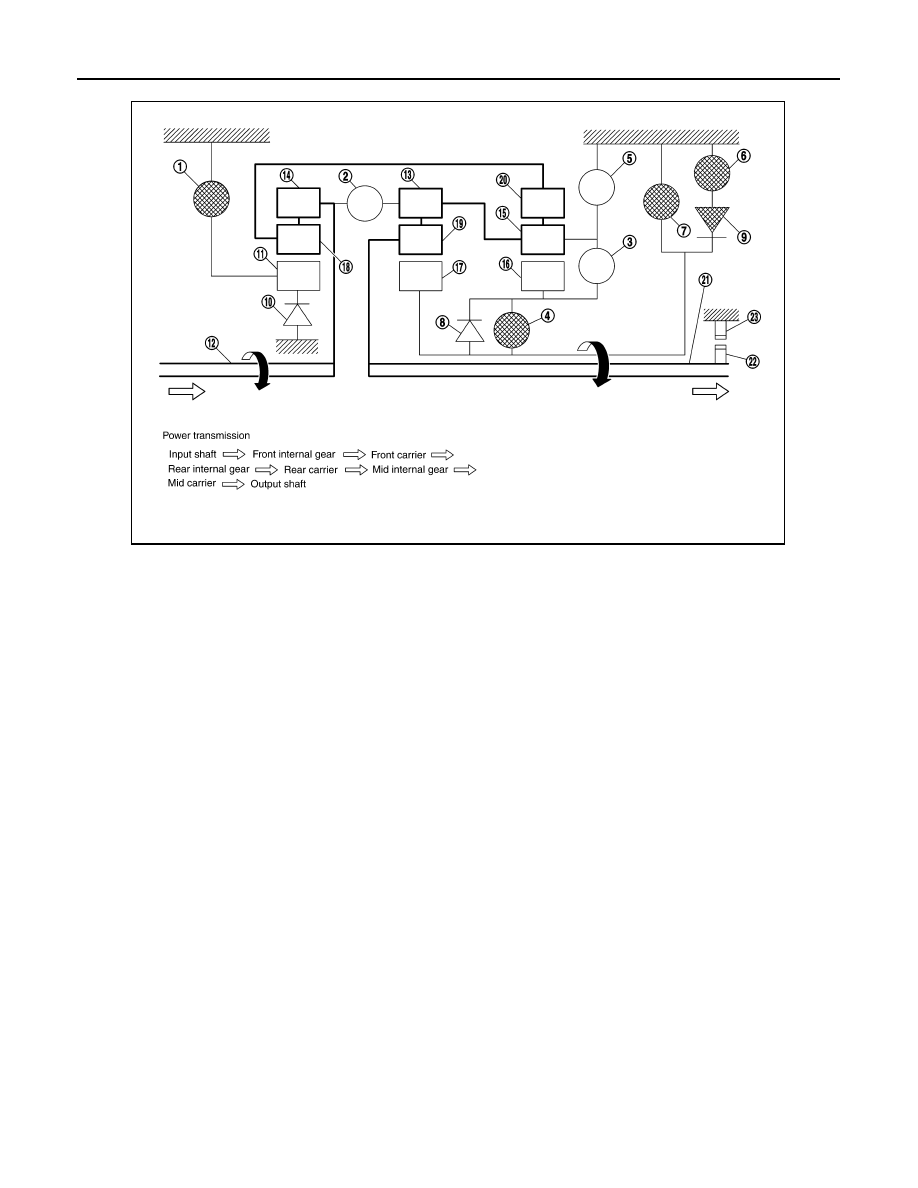
• The forward brake and the forward one-way clutch regulate reverse rotation of the mid sun gear.
• The 3rd one-way clutch regulates reverse rotation of the front sun gear.
• The direct clutch is coupled and the rear carrier and rear sun gear are connected.
• During deceleration, the mid sun gear turns forward, so the forward one-way clutch idles and engine brake is
not activated.
1.
Front brake
2.
Input clutch
3.
Direct clutch
4.
High and low reverse clutch
5.
Reverse brake
6.
Forward brake
7.
Low coast brake
8.
1st one-way clutch
9.
Forward one-way clutch
10. 3rd one-way clutch
11. Front sun gear
12. Input shaft
13. Mid internal gear
14. Front internal gear
15. Rear carrier
16. Rear sun gear
17. Mid sun gear
18. Front carrier
19. Mid carrier
20. Rear internal gear
21. Output shaft
22. Parking gear
23. Parking pawl
SCIA1513E
2010 Pathfinder